Does anyone have a circuit for a homemade “tie breaker” system? A teacher at my son’s school is having a quiz contest where kids have to “buzz in.” I need to build a circuit that can indicate who pressed a button first. I would prefer to use simple electrical components for this project as I am not really adept at programming microcontrollers.
#7152
Alex Ferguson
Pittsburgh, PA
Please log in to post an answer.
Answers
The tiebreaker circuit could also be implemented with relays, which wouldn't require any soldering or breadboarding. A relay would be required for each contestant, with as many poles per relay as there are contestants. The schematic I provided uses four 4-pole relays. For a higher number of contestants, relays could be ganged together (wire the coils in parallel) to obtain more poles. For each relay, pushing the corresponding button activates the coil; the normally-closed contacts of the other relays in series ensure that only one coil can be activated at once. A normally-open contact of the same relay placed in parallel with the button latches the coil so that it will stay on when the button is released. A normally-closed reset button (which could also be the on/off switch) will unlatch the relays.

Low cost multi-pole relays with screw-down wire terminal sockets can be found on eBay or at electronics surplus stores. Some even have indicator lights which would eliminate the need for separate lamps. Supply voltage would be selected to match the relay coil voltage. Since relays are mechanical devices, they have a finite switching time, which is usually on the order of milliseconds. It is theoretically possible that two button presses extremely close together could cause more than one relay to latch. To test this I put together a system like I described but with only two relays and buttons instead of four. The good news is that I was unable to make both relays latch on, even after many attempts at pushing both buttons simultaneously.
John Collier
Wooster, OH
This is one of the simplest quiz circuits I've come across. I've built several versions. Some as simple as the first one, and a very complex one, but still using the same concept of parallel SCRs. www.techlib.com/electronics/games.html
Ken Moffett
St Paul, MN
There is a very simple old school tie breaker indicator circuit which I have used several times, It's inexpensive and works well.
Use a small neon lamp such as an NE2, and NE51 or any of the other types available. Use as many lamps as necessary for the number of stations desired. A latching type pushbutton or toggle switch in series with each lamp located at each players position. The trick here is that all of the series lamp/switch combinations are paralleled from one power source that being the 120 VAC line with a 68k-100k 1/2 watt resistor in series with one side of the line.
The principle is simple, with all of the switches off, there is no drop across the resistor. The first lamp that is energized, fires and pulls the voltage on the bus down to the point where no other lamp can fire. Neon lamps need a high voltage (generally around 65 volts) to fire but once fired will stay illuminated on much lower voltage, lower than any other lamp can fire.
Ron Schacht
Kensett, Iowa
The attached circuits (Figures 1 and 2) should do the trick. Each student station is equipped with a normally-open pushbutton switch connected to the instructor’s console via a cable of suitable length, terminating at a connector.
The instructor’s console consists of a bank of LEDs, one per student; a Master Reset pushbutton switch; and a suitable number of two-pin connectors into which the student pushbutton cables are plugged.

Each student readout consists of a “D” flipflop, an AND gate, an inverter, a diode, and an LED, plus associated wires, resistors, and capacitors as shown. The LED can be red or green, of any physical shape, having a maximum continuous current rating of 20 mA. The circuit is set for about 10 mA through the LED, which is very conservative and will provide quite adequate illumination.

The CMOS 4013B contains two “D” flipflops as shown, in a 14-pin package; power pins are 14(+) and 7(-). The CMOS 4081B contains four two-input AND gates as shown, in a 14-pin package; power pins are 14(+) and 7(-). The CMOS 4049B contains six inverters as shown, in a 16-pin package; power pins are 1(+) and 8(-). Be careful of this — applying “+” power to pin 1 is unconventional, but this is the way that the package is designed.
The circuit works in the following manner:
- Assume that the Master Reset button has been pushed on the teacher’s console, asserting the +RESET bus. This forces all “D” flops to be reset, and all LEDs to be extinguished. The voltage level on the (diode-OR’d) -INHIBIT bus applies a logic-high signal to the D inputs of all flipflops, as well as to one of the inputs of each of the AND gates.
- The first student to press a button enables the AND gate for her/his receiver, which sets his/her “D” flipflop to the “on” state. Immediately its Q-bar output goes low, pulling down (asserting) the -INHIBIT bus, which presents a logic-low signal to the D inputs of all flipflops and disables all of the AND gates, thereby inhibiting further clocking pulses to all “D” flipflops.
This ensures two things:
- that subsequent button depressions by other students cannot set the “D” flipflop in their receiver circuits to the “on” state; and
- that a second depression of the winning student’s pushbutton will not set the “D” flipflop in her/his receiver to the “off” state, thereby negating her/his vote and inadvertently opening the process to a new round of voting.
The two resistors shown relative to the output and one input of each AND gate provides hysteresis and reduces noise sensitivity. As implemented, the input signal delivered to the 12K ohm resistor must rise above eight volts or fall below 4.5 volts before a high or low output level (respectively) will be realized at the gate output (assuming that the remaining input to the AND gate is held high).
The contacts in each pushbutton are debounced with a paralleled R-C network.
The 12 VDC power can be provided by a small wallwart regulated power supply. Anything that will provide 100 mA or more will suffice.
Construction Suggestions:
- Note that the integrated circuit (IC) package schematics show the two 4013B elements, the six 4049B elements, and the four 4081B elements, and that each IC is bypassed by a 0.01 µF disk ceramic capacitor, to be connected with the shortest possible leads across the power input terminals of the IC.
- Pin assignments in the circuit schematic are illustrative; consult the IC package schematics for actual pin-outs for each circuit element in any particular IC.
- The tie-breaker circuit shows two 4049B elements connected in parallel. Both elements must reside in the same IC package.
- Diodes are 1N914 or 1N4148 signal diodes. All resistors are 1/4 watt carbon composition. With one exception, the capacitors are all disk ceramic, of any type (Z5U or better), 25 volts rating. The polarized capacitor is tantalum, and is to be connected directly across the 12V power input to the circuit board.
- While the circuit schematic shows only three “student receiver” circuits, there does not seem to be any reasonable limit to the number that might be included, so long as +12V, circuit ground, and the +RESET and -INHIBIT busses are extended to all.
- The input pins of all unused circuit elements must be connected to ground.
- The student switches should be connected to the main console using twisted-pair cable to ensure minimum noise sensitivity. Mount the R-C debounce circuit directly across the pushbutton pins.
- Dual-in-line package (DIP)-type ICs and IC sockets are recommended.
Datasheets for the three ICs may be found at:
www.nxp.com/documents/data_sheet/HEF4013B.pdf
www.nxp.com/documents/data_sheet/HEF4049B.pdf
www.nxp.com/documents/data_sheet/HEF4081B.pdf
A 1N914 diode datasheet is located at: www.vishay.com/docs/85622/1n914.pdf
Parts are all readily accessible from Digi-Key, Mouser, Jones Associates, Newark, etc.
Peter A. Goodwin
Rockport, MA
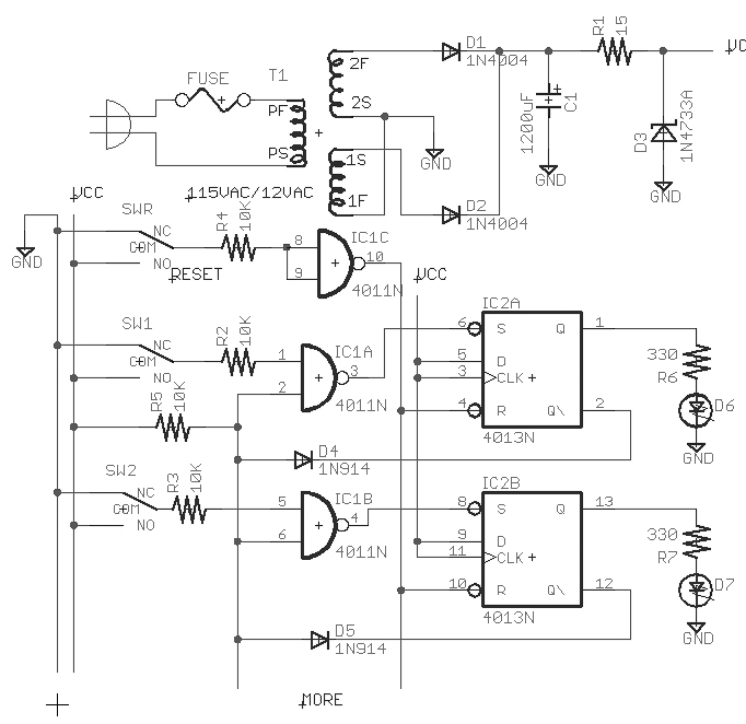
I have modified a circuit that I used 27 years ago, which consists of a two input NAND (cd4011n) driving a set-reset flip-flop (cd4013n). The push button switch is connected to one 4011 input and goes high when pressed. The other input of the 4011 is held high by a resistor to VCC.
When the button is pressed, Q of the 4013 goes high, lighting the LED. At the same time, the NOT-Q output goes low and locks out all 4011 inputs including the one that pressed the button. The circuit remains in this state until the reset button is pressed.
Russell Kincaid
Milford, NH
My home alarm system has a motion sensor that has failed and the alarm company wants $89 for a new one! I removed the bad one and it has screw terminals labeled:
- GND
- 12V
- ALARM COM
- ALARM NC
- TAMP1
- TAMP2
The simple PIRs I find for use with the Arduino are 5V and they don’t have “tamp” pins. Can someone provide a schematic on how to hook up one of these low cost replacements?
#7151
Christopher Randazzo
Worcester, MA
Please log in to post an answer.
Answers
There are several reasons an Arduino hobby type PIR is not a good substitute for a commercial PIR motion sensor.
- You will need to step down the 12V to 5V with a voltage regulator. Coincidentally page 78 of the July 2015 N&V Tech Forum has answers for a 5V regulator question .
- You will need to add a 5V relay from the TTL output of your Arduino PIR so that you can provide floating form C (COM and NC) contacts for Alarm COM and ALARM NC. Normally the ALARM contacts are closed unless an alarm condition is sensed. All sensors and switches in the ALARM loop are wired in series in a burglar alarm. Color code may vary, but in my experience a red and a black wire were used. You should pay attention to the colors used in your system.
- Unlike a commercial PIR, the Arduino PIR does not have a optical shield and/or shutters to adjust the beam width. As such, it will have a broader sensitivity and be susceptible to false alarms from moving persons or objects outside windows or pets inside. Additionally, it may be blinded from ambient light sources.
- The terminals marked TAMP 1 and TAMP 2 are tamper switch connections. Normally the tamper circuit is closed unless the sensor case is opened. In my experience a white and green wire were used for tamper circuits. Yours may differ. If the tamper switch is opened in a commercial alarm system, a supervisory signal is sent to the alarm office and a technician is sent to inspect the system. This is to prevent a would be burglar from opening the sensor and tampering with wires or placing tape over the PIR sensor. In a residential alarm system, a trouble light will appear locally at the control panel. With the above information, you can make the Arduino PIR function, however the possibility for false alarms will be much greater unless you are willing to spend the time constructing a proper light shield.
The $89 quoted by your alarm company sounds fair, and is an even better deal if they install it for that price. If you are under contract for alarm reporting to the central office, modification of the system may create problems with the agreement. You may be able to find an equivalent commercial sensor on E-Bay for a good price if you insist on replacing it. Personally I would stick with a commercial PIR for this application.
Joe Leikhim
Oviedo, FL
You only need to connect four wires for a burglar alarm motion detector to work properly. “GND” and “12V” are voltage for the motion detector - 12V is the positive, GND is the negative. “ALARM COM” and “ALARM NC” connect to the zone input on your burglar alarm panel. Typically, there is no need for polarity because this is a simple switch - with no motion in the area the switch is closed, motion is detected the switch opens.
“TAMP1” and “TAMP2” are connected to a mircoswitch within the motion detector housing that activates your alarm if someone were to remove the cover - called a “tamper.” If anything is connected to these terminals, you can simply twist the wires together, complete the circuit, and cap them off. It is not necessary to utilize the tamper feature and is often not recommended.
But, I would avoid any type of “inexpensive” replacements for your alarm system motion detector. One of the major sources of false alarms in burglar alarm systems tends to be the motion detector. Installing a motion detector not specifically designed for burglar alarm use may end up causing false alarms with your system and depending on your jurisdiction, fines from the local police department from the dispatching of those false alarms. Most burglar alarm motion detectors are designed to limit false triggers - so I would suggest going that route.
I did a quick search and could find a reliable motion detector listed for burglar alarm use for $25. Easy enough to replace yourself, just make sure you seal up any penetrations in the housing where the wire and screws go through. Spiders love to make homes in these and that will also cause false alarms.
Alternately, $89 may not be a bad price for your alarm company to replace the detector if that includes the labor. Nobody wants to work for free after all! Plus you can get them to quickly check your system to make sure it is communicating properly to your monitoring company and everything is working correctly.
Eric D. Bailey
Cecilton, MD
TAMP1 and TAMP2 are the tamper contacts. They are normally closed as long as the device is not being tampered with. They are just ‘dry’ contacts and could be connected to the Arduino.

Marc Forgey
Seattle, WA
I’ve read that bipolar transistors are current devices and MOSFET transistors — like old-fashioned vacuum tubes — are voltage-operated devices.
Although I understand the distinction conceptually, what does that mean from a practical perspective? For example, does this mean that bipolar are best for high power applications and MOSFETs are best for low voltage applications?
#6153
Dale Schwan
Douglas, ND
Please log in to post an answer.
Answers
Mosfets come in many flavors: there are N-type and P-type of course but there are enhancement mode and depletion mode. Enhancement mode are off at zero gate voltage; you have to apply a positive gate voltage for N-type or a negative gate voltage for P-type to turn it on. N-type mosfets are available with drain voltage ratings from 30 V to 800 V or more. Most mosfets are designed for switching; an 800 V, 10 amp device would quickly burn up unless it could turn on and saturate even quicker.
Mosfets are characterized by their saturation resistance which can be very low (like .01 ohms). Bipolar transistors on the other hand, are characterized by their saturation voltage which can’t get as low power as mosfets. The threshold voltage (the point where the transistor just turns on) is not well controlled so you can’t really know what the drain current will be at a particular voltage. That makes it difficult to design a linear circuit. I avoid that problem by using bipolar transistors in linear circuits, or using pulse width modulation in a switching circuit which can be filtered to produce an analog signal.
Depletion mode mosfets are on at zero gate voltage and you have to apply a negative gate voltage to N-type to turn it off. Junction fets are also depletion mode devices and the zero gate voltage drain current is not well controlled so they are usually binned and labeled so you can have some idea of what you are designing with.
Russell Kincaid
Milford, NH
I am interested in building the shortwave radio shown in the schematic https://www.nutsvolts.com/uploads/wygwam/TF_2154_SW_Radio.jpg from Michael Williams Tech Forum question #2153 on page 78 of the February 2015 issue. However, I need more information, specifically the dimensions of L1 — length, diameter, etc., and the frequency range of the receiver.
I’m also seeking information on the coil data, size, number of turns, etc., for the shortwave and broadcast band coils for the Allied Space Spanner regenerative receiver, as well as modifications (plug-in coils VFO) that would increase the frequency coverage above and below the stock range of 6 to 12 MHz on the shortwave section of the receiver.
#6152
Bradley Flener
Central City, KY
Please log in to post an answer.
Answers
First I cannot help you with the information you are looking for on the Allied Space Spanner receiver. However, the other part of your question is about calculating the information for coil L1. The formula for calculating inductance needed for a resonate frequency as the value of the capacitor is shown.
To calculate the inductance of L1 for the standard broadcast band (535KHz to 1700KHz), L= the inductance in µH, f= the frequency in MHz, and capacitance is in pF. Since the capacitance is given as 10 to 365pF, and we know the minimum frequency is 535KHz (or .535MHz), L=25330/(.535 x .535 x 365). L=242µH. In the above formula, we replace the C an L can be interchanged. So if we know the value of the capacitance we can calculate the value of the inductance and visa versa.
With the calculated inductance (242µH) and the maximum frequency of the broadcast band (1700KHz or 1.7MHz), C=25330/(1.7 x1.7x242). C=32pF. So, with a coil wound very close to 242µH, the receiver would cover the standard broadcast band, and a little higher.
Let’s now calculate the number of turns of #30 and diameter of the coil needed to get 242µH. N=√(L(9r+10l) )/r is the formula for calculating the number of turns on a coil, but we have to know the values of radius, and the length of the coil. With a coil, the larger the diameter and the closer the turns are together increases the inductance. r = the mean radius, l = the length of the coil.
I recently did a project very similar to this so I have first hand knowledge of the approximate dimensions of the coil. Looking in a wire table, I find that #30 wire will make approximately 90 turns for a linear inch. I then choose the l of the coil of 1 inch long and the diameter to be 2 inches, so r=1. After plugging the values into the formula, 67 turns is the result. So close wind 67 turns of #30 wire on a 2 inch diameter form and then loosen the turns slightly, and spread them out so the length of the coil is 1 inch. With this information you can calculate the other resonate circuits.
Ned Stevens K7ELP
Saint George, UT
L1 value us very close to 250µH. You could wind one on a form, but buying on would be much easier as the magnet wire may be much more expensive.
Ned Stevens
St. George, UT
In a recent issue of NV, Roger Secura wrote the article “How to Use a Transistor as an SPST Switch.” My question is how can an STDT switch be made using transistors, FETs, or other non-mechanical components? If it is possible, please post a circuit.
#6151
Don Czyzyk
Santa Clara, CA
Please log in to post an answer.
Answers
It’s pretty simple... you just need another switch that’s connected to the output of the first switch. These switches are commonly called Inverters, meaning that the output is inverted from the input. This means that for a high level input, the output is a low level, and vice-versa. So, all we need to create a bi-level output from a single input is a second inverter connected to the output of the first inverter. Bipolar transistors and FETs act pretty much the same way, the difference being that bipolar transistors are current-driven, whereas FETs are voltage-driven.
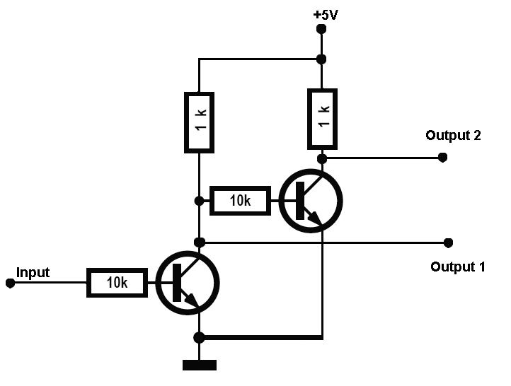
If you need more theory on transistor circuits, I refer you to a series of articles by Ray Marston in Nuts&Volts titled “Bipolar Transistor Cookbook”. This is an 8-part series that N&V has graciously made available online. www.nutsvolts.com/magazine/article/bipolar_transistor_cookbook_part_1. Be sure to have plenty of reading time available, because it contains a train-load of information. I’ve attached a circuit image depicting how to connect two transistors as an SPDT switch.
David Mason
Hazel Green, AL
I have a drill press that has a five amp fuse that recently has started to blow on just about every project. I am not working on harder material and the bits are sharp, so I don't think its increased torque from friction which leaves the electronics. As this is simply a motor and a power switch, I can’t imagine what might be causing the increased current draw. Suggestions?
#5154
Liam Olivo
Saginaw, MI
Please log in to post an answer.
Answers
One thing that was not mentioned was a start run capacitor. Does the motor have a "hump" on it? If it does, there is a capacitor under it and it is probably bad. You can check it with an ohm meter when it is disconnected. See if the capacitor has not charged and causes the ohm meter to give some funny reading, like a negative reading. If it is shorted or open it is defective.
Doug Chason
Auburn, AL
Mr. Olivo is experiencing nuisance fuse blowing in his drill press. The problem may well be that the fuses that he has been using cannot tolerate the inrush current demand of the motor. At the instant of power application, the magnetic state of the motor core may be such that the first half-cycle of utility power drives it into saturation.
Assuming that the fuse is a 1/4” x 1-1/4” cartridge fuse, a Bussmann MDL-5 fuse will open at five amperes, but will tolerate more than one hundred amperes during a one-half cycle of utility power. See the time-current curves for this family on data sheet #2004, which is downloadable from web page www.cooperindustries.com/content/public/en/bussmann/electrical/products/electronic_smalldimension/elx_1_4_x_1-1_4_/mdl-v_mdl.catalog_numbers_(amps).brands.cooper_bussmann.html
If the fuse is another size, check with your local electrical jobber for an appropriate fuse having similar inrush tolerance. Good luck.
Peter A. Goodwin
Rockport, MA
Does the dill press sound any different? Maybe the bearing in the motor is wearing out causing the increased load.
What about the cord? Has it been pinched/damaged in any way? Or even the outlet that it is plugged into, are there visible signs of scorching?
Lastly, how old is it? Could the motor be electrically failing? Things to consider beyond stresses due to operator use.
Justin J
King City, CA
If this is just an on/off, switched drill press, then you definitely have an excessive friction issue. If a good lubrication doesn’t help, then the brushes or commutator in the motor are worn and binding.
Michael Herman
La Quinta, CA
Worn bearings could be allowing the armature to rub on the stator. Remove the belt and try to move the motor shaft; if it moves at all, it is bad.
Russell L. Kincaid
Milford, NH
:You don't say what type of fuse you are using but if it is a buss type glass fuse, you might want to make sure you are using a slow-blow type fuse for your drill press.
Gene Sellier
Fairhope, AL
Is there a simple circuit that would allow a normally open pushbutton to turn on a relay when pressed, and then turn it off when pressed again?
#5153
Isaac Wright
Maumee, OH
Please log in to post an answer.
Answers
When the circuit is first energized, C charges to 1/2 Vcc through voltage divider R1/R2. When the button S1 is pushed, C discharges through the relay coil. It pulls in, and the relay is held closed by the current through R1 and the relay coil. When the button is pushed again, C, now fully discharged by R2, goes across the relay coil making it drop out and returning the circuit to where it started.

Mike Callaghan
via email
In essence, this is a flip-flop. Push the button and the state of the flip-flop will change. Adjust the values to your needs.

Al Jaszek
Needham, MA
It’s funny you should post this request. I just happen to have an article submitted to Nuts and Volts utilizing this exact same situation that will hopefully be appearing in an upcoming issue!
 In the meantime, here is the (modified) relevant portion of the schematic as you requested. The 74LS109 is a J-K Positive-Edge Triggered Flip-Flop. The input is tied to normally tied to ground, but when you press the switch that input is momentarily brought high, triggering the flip-flop, toggling the relay between it’s on and off states. R2 and C1 are to debounce the switch and prevent multiple false inputs.
Derek Tombrello
Columbiana, AL
Use the push button switch to toggle a JK flip-flop.
Lance Corey
via email
It can't get any simpler than two resistors, one capacitor, and the relay.
Mike Callaghan
La Crescenta, CA
Here is a simple circuit that can be used to toggle a relay using one switch. A relay with a 12 VDC is used however the relay contacts can control a larger voltage if needed.

Craig Kielhofer
Wheeling, IL
Look into a switch debouncer such as the MAX6816 and JK, or T flip-flops to drive the gate of a low side switch on your relay. The output of the switch debouncer could drive the clock of a T, or properly configured JK, flip-flop. Don’t forget the protective diode across the relay in order to clamp the voltage when turning the relay on/off. I hope this helps.
Justin J
King City, CA
Here are two circuits that should do want you want: Grove-2 @10 from: www.seeedstudio.com (YES, there are 3 e’s) Cebek I-9 @ $4 from www.mcmelectronics.com
Also, there are a variety of electro-mechanical relays available at many sources. These do not need a circuit to latch but when the relay is activated, it toggles a switch from off to on.
Michael Herman
LaQuinta, CA
What would be the most efficient way to reduce the voltage from a nine volt battery to 5V? I could use a 7805 but it seems to bleed off a lot of power as heat. Is there a more efficient circuit or part?
#5152
Alan Vallo
Piedmont, SC
Please log in to post an answer.
Answers
Take a look into DC-DC buck converters. Many of the IC manufactures offer low part count devices, and depending on your load requirements, may offer a completely integrated solution.
Things to consider when selecting your buck converter:
1. Internal switch/es to the IC — ease of implementation
2. Synchronous design — higher efficency
3. Load capabilities — This is one of the most important things to consider, especially with an integrated design. You want to select an IC that meets your load requirements, ie output current, but not something that blows them out of the water.
In other words, If your output requirements are 5V @ 100mA (0.5W), don’t choose a device capable of 10W, or 2A at 5V. The reason being is, these devices are more efficient when operated at the loads they were designed for.
One last thing, review the EVKIT the manufacturer has available for the device. These are really good starting points for layout and design with the device. I hope this helps.
Justin J
King City, CA
A very economical solution are the LM25XX switching regulators on a board, which sell cheap from MPJA or the internet. I also use the MC34063 which is often found in the “12 volt to 5 volt” cell phone adapters at your local thrift store, but easier to work with purchased new.
For low current applications, my favorites are the encapsulated 1W or 3W switching DC-DC regulators from CUI, Murata, etc. via Digi-Key.
Jim Lacenski
Bellevue, WA
The UA78s40 is an old switching regulator that is obsolete, but parts are available on Ebay. The datasheet has a schematic for 26 volts to 10 volts but you only need to change two resistors for 5 volts output: R1 = 30K, R2 = 10K.
A more modern solution is the LM2576 buck regulator. It only uses two capacitors, a diode and an inductor for external components. The datasheet has a schematic that you can use directly.
The package is TO-220-5, Mouser part number is: 926-LM2576T-5.0/nopb, cost: $2.82. The IC is good for 3 amps but if your load is less than 20 mA, it would not be a good choice.
Russell L. Kincaid
Milford, NH
Yes, the 7800 and 7900 series seem to just dissipate heat to drop the voltage. Try the LM2940-5 - I found them at Jameco for $1.39 each......
Schneids
via email
You might try using an LDO regulator like the LM2596S chip. I bought a 1.5V-37V DC/DC buck convertor from MPJA for $1.95 to reduce 12V to 9V and it runs very cool.
Gene Sellier
Fairhope, AL
Can one of your experienced electronic engineers recommend replacement plastic transistors (maybe a la PN2907) which are easily available, in order to substitute Q1, Q2, Q3, and Q4? I want to totally eliminate 2SB54 transistors WITHOUT any draconic and/or extreme changes to the original diagram (below) for this (push-pull) phone amplifier I'm using, by attaching a suction cup to my (landline) phone's receiver.

I'm well aware of the existence of other phone amplifiers (built around the LM386) which are easier to build with fewer parts, but I'm only interested in this diagram, as I’ve already built it in the past — not only as a phone amp with ample volume (which also works very well as a P.A. system), but as a wired intercom.
#5151
Nate Franklin
Schererville, IN
Please log in to post an answer.
Answers
Mr. Franklin desires to reproduce a known circuit design that uses four 2SB54 transistors. The 2SB54 is an obsolete part. Furthermore, it is a germanium device. Mr. Franklin asks if a 2N2907 or similar silicon PNP device could be used instead.
Substituting silicon devices for germanium devices is a non-trivial exercise:
• The no-signal emitter-base junction voltage of germanium devices is about 0.3v, while that of silicon devices is about 0.7v. In a linear circuit such as that presented here, bias voltage appropriate to the transistor material type must be applied to overcome the junction voltage offset.
• Germanium transistors exhibit current leakage. This is often sufficient to provide self-biasing. Silicon devices have negligible leakage in the circuit under consideration, so external biasing must be considered.
The simplest thing to do is to replace the 2SB54 with another germanium part. The NTE100 device, manufactured by NTE Electronics, has characteristics that are similar to those of the 2SB54. It is available from multiple distributors including Newark Electronics, Fry’s Electronics, and Online Components, or you might try eBay. Pricing runs from about four to seven dollars per device. A data sheet, which includes a basing diagram, is available from NTE Electronics.
Good luck.
Peter A. Goodwin
Rockport, MA
Those transistors date back in time quite a ways, as does the circuit! The 2SB54 is a Germanium, PNP unit. RadioShack has a drop-in generic on their website as part #55051964.
You could also toss out everything between the microphone and the speaker and connect a LM380 integrated circuit. I have an old transistor substitution guide in storage so contact me if you need a further referral. Good luck.
Michael Herman
LaQuinta, CA
Q1 and Q2: the circuit is a self-biasing design. MPSA56 should work fine, even though these are silicon transistors instead of germanium.
The output stage (Q3/Q4): 2N4918 or BD136 would be my preference. You will need to increase the value of R6 (try 330 ohms) to reduce crossover distortion due to the larger Vbe drop of the silicon transistors. Note that this output stage has no temperature compensation and is subject to thermal runaway.
Better transistor designs of this era used a thermistor for temperature compensation. See Wikipedia’s thermal runaway entry, bipolar junction transistors, for more insight. I would still LM386, which eliminates the (likely) hard to get transformers too. More power? Look at the numerous class-D single chip power amps.
Jim Lacenski
Bellevue, WA
The circuit is well designed with feedback in the first stage to stabilize its current and an emitter resistor to limit the current in Q2. The output transistors, Q3 and Q4 are class B so draw no current until driven by audio. I simulated the Q1, Q2 circuit and it works perfectly with no changes using 2N2907 transistors. Q2 collector current is 4.8 mA which is sufficient to drive the output transistors to watts of power.
Russell Kincaid
Milford, NH
The main problem is the transistors are germanium and not silicon. So, I doubt you could plug in silicon transistors and have it work properly [although if you’re desperate, you might give it a try anyway].
The transistors have pretty much been discontinued from what I could tell. NTE makes a sub that should work for you — NTE102. You should be able to find them at several places. I checked Allied and they had some in stock — but on the pricey side.
You should be able to find a newer circuit at some electronics site that uses newer transistors or op amps.
Schneids
via email
I would consider the 2N3906. The Hfe (100 min, 300 max) puts this device near the 2SB54 specified Hfe of 140.
Mark Strauch
Livermore, CA
The 2SB54 is a fairly ordinary Germanium PNP transistor. It could be replaced with any general purpose Silicon PNP like the PN2907, 2N3906 or BC327. You will need some changes as silicon transistors are harsher than germanium types:
(a) you will have to increase the value of R6 to 1K to bias the output stage (maybe 1K5 to get more power out) keep an eye on the quiescent current, it should be < 10mA.
(b) (optional) to improve crossover distortion , remove R5, and use 33K resistors between base and collector of each of Q3 and Q4 (just like R1)
(c) (optional) to make it less tinny, put a 22ohm in series with C3 (other values will work like a tone control)
(d) (optional) to flatten out the response , try a 47K for R1 , (values in the range 10K to 100K could be tried) this also affects the gain and interacts with the source impedance. The above values were determined by simulation to give a better result than the original values, however the simulation uses perfect transformers. If you get RF oscillations, try a 1nF from base to collector of Q2 or 470pF from base to collector of Q3, Q4, or ferrite beads on the emitters of Q1 or Q2.
Bob Turner
Salamander Bay, Australia
The swap you suggest will require some adjustment of transistor bias. The 2SB54 are Ge. material with 0.15 to 0.2V base emitter bias. The PN2907 and similar are Si. with a 0.65 to 0.7V base emitter bias requirement. R2 and R6 will likely need to be increased in value. Quick estimate for R6 at 0.7V is around 1.2K The collector feedback biasing makes the calculation of R2 value more difficult and might not have to be changed due to the feedback.
Search for similar circuits using silicon transistors to get some better resistor values. Note that Q3 and Q4 require a little forward bias to prevent crossover distortion. I would expect considerable distortion if the biasing resistors are not modified to account for differences in GE. vs. Si material GWS
George Shaiffer
Colorado Springs, CO
A 2N3906 should work OK. It has the same general characteristics as the 2SB54 transistors, except for being silicon instead of germanium, greater power dissipation and slightly higher hfe (100 as opposed to 80).
Gene Sellier
Fairhope, AL
I would try a PN2222 which is an old standby PNP transistor. I don’t think there is anything special about the 2SB54, it is just older. Jameco sells them for ten cents a piece. Part no. 28628. Download the data sheet and watch the pin locations.
Ron Newton
Carson City, NV
I have a Marlin P. Jones DC motor speed controller (Part 31566MD, 6-24 volts, 20 amps max). I need to add an over current circuit to it. I inserted two 0.1 ohm/five watt resistors in series with the motor –lead and the M-connection on the controller. My scope displays a steady 0.6 volts DC level across it. The PWM waveform changes from 2 µsec to 40 µsec in length as the output of the speed controller is increased from 0 to 3 amps, while my DVM displays 0.02 VDC to 1.3 VDC for the same range of output.
So, the question is “What kind of circuit can I add across the resistors to get a VDC reading?” I have tried an NPN transistor, base lead to the motor –lead, and the emitter lead to the M- connection. (With a 10K collector resistor to +12 VDC.) The collector voltage went from +12 volts to +3 volts as the controller output went from 0 to 3 amps.
Next, I connected the collector voltage to an LM324N quad op-amp set up as a voltage comparator. The +lead of an LM324 went to a 200K pot, connected between +12 VDC and Gnd. The transistor’s output went to the –input of the same op-amp. A 1M ohm resistor is connected from output to +input for hysteresis. (This output should go high to set a CD4013N flip-flop at an over current condition.)
The problem is that the output of the op-amp’s output does NOT change at the point when the voltage at the +input is greater than the –input. The op-amp’s output changes as the voltage from the transistor decreases. I used the LM324N auad op-amp because it has four op-amps in one chip, and it works with a single +12 VDC supply. It would be helpful if the new circuit could use it also, but not necessary. I could use a PIC16F628 or an Arduino Nano, if you design with them.
#4153
Patrick Fleming
Hoffman Estates, IL
Please log in to post an answer.
Answers
I’ve found the 31566 schematic. The simplest solution, that I’ve used in similar circuits, is to use a ZXCT1009, this is a 3 terminal current sensor. So put your 100mR shunt in the positive line, attach the ZXCT1009 across it, and a current proportional to the motor current (about 1/1000 actually) flows out of the third pin to ground. Simply attach a resistor, say 1K ohm to ground and you can read the motor current off this.
The most important advantage of this chip is the sense resistor can be grounded at the Arduino, so you won’t be measuring any errors due to voltage drop in the ground wiring. The datasheet shows how to use it, and provides calculations on how to use PCB traces as current shunts.
Bob Turner
Salamander Bay, AUstralia