The attached circuits (Figures 1 and 2) should do the trick. Each student station is equipped with a normally-open pushbutton switch connected to the instructor’s console via a cable of suitable length, terminating at a connector.
The instructor’s console consists of a bank of LEDs, one per student; a Master Reset pushbutton switch; and a suitable number of two-pin connectors into which the student pushbutton cables are plugged.

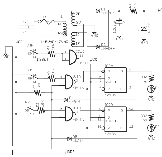
Each student readout consists of a “D” flipflop, an AND gate, an inverter, a diode, and an LED, plus associated wires, resistors, and capacitors as shown. The LED can be red or green, of any physical shape, having a maximum continuous current rating of 20 mA. The circuit is set for about 10 mA through the LED, which is very conservative and will provide quite adequate illumination.

The CMOS 4013B contains two “D” flipflops as shown, in a 14-pin package; power pins are 14(+) and 7(-). The CMOS 4081B contains four two-input AND gates as shown, in a 14-pin package; power pins are 14(+) and 7(-). The CMOS 4049B contains six inverters as shown, in a 16-pin package; power pins are 1(+) and 8(-). Be careful of this — applying “+” power to pin 1 is unconventional, but this is the way that the package is designed.
The circuit works in the following manner:
- Assume that the Master Reset button has been pushed on the teacher’s console, asserting the +RESET bus. This forces all “D” flops to be reset, and all LEDs to be extinguished. The voltage level on the (diode-OR’d) -INHIBIT bus applies a logic-high signal to the D inputs of all flipflops, as well as to one of the inputs of each of the AND gates.
- The first student to press a button enables the AND gate for her/his receiver, which sets his/her “D” flipflop to the “on” state. Immediately its Q-bar output goes low, pulling down (asserting) the -INHIBIT bus, which presents a logic-low signal to the D inputs of all flipflops and disables all of the AND gates, thereby inhibiting further clocking pulses to all “D” flipflops.
This ensures two things:
- that subsequent button depressions by other students cannot set the “D” flipflop in their receiver circuits to the “on” state; and
- that a second depression of the winning student’s pushbutton will not set the “D” flipflop in her/his receiver to the “off” state, thereby negating her/his vote and inadvertently opening the process to a new round of voting.
The two resistors shown relative to the output and one input of each AND gate provides hysteresis and reduces noise sensitivity. As implemented, the input signal delivered to the 12K ohm resistor must rise above eight volts or fall below 4.5 volts before a high or low output level (respectively) will be realized at the gate output (assuming that the remaining input to the AND gate is held high).
The contacts in each pushbutton are debounced with a paralleled R-C network.
The 12 VDC power can be provided by a small wallwart regulated power supply. Anything that will provide 100 mA or more will suffice.
Construction Suggestions:
- Note that the integrated circuit (IC) package schematics show the two 4013B elements, the six 4049B elements, and the four 4081B elements, and that each IC is bypassed by a 0.01 µF disk ceramic capacitor, to be connected with the shortest possible leads across the power input terminals of the IC.
- Pin assignments in the circuit schematic are illustrative; consult the IC package schematics for actual pin-outs for each circuit element in any particular IC.
- The tie-breaker circuit shows two 4049B elements connected in parallel. Both elements must reside in the same IC package.
- Diodes are 1N914 or 1N4148 signal diodes. All resistors are 1/4 watt carbon composition. With one exception, the capacitors are all disk ceramic, of any type (Z5U or better), 25 volts rating. The polarized capacitor is tantalum, and is to be connected directly across the 12V power input to the circuit board.
- While the circuit schematic shows only three “student receiver” circuits, there does not seem to be any reasonable limit to the number that might be included, so long as +12V, circuit ground, and the +RESET and -INHIBIT busses are extended to all.
- The input pins of all unused circuit elements must be connected to ground.
- The student switches should be connected to the main console using twisted-pair cable to ensure minimum noise sensitivity. Mount the R-C debounce circuit directly across the pushbutton pins.
- Dual-in-line package (DIP)-type ICs and IC sockets are recommended.
Datasheets for the three ICs may be found at:
www.nxp.com/documents/data_sheet/HEF4013B.pdf
www.nxp.com/documents/data_sheet/HEF4049B.pdf
www.nxp.com/documents/data_sheet/HEF4081B.pdf
A 1N914 diode datasheet is located at: www.vishay.com/docs/85622/1n914.pdf
Parts are all readily accessible from Digi-Key, Mouser, Jones Associates, Newark, etc.