While on vacation, I managed to lose the power supply wall wart to a cheap vintage portable no-name brand shortwave radio. On the back of the radio, the power jack says 9 VDC and has a C shaped circle and a dot in the center with a plus sign on the dot. I’m pretty sure this means nine volts; positive tip. However, what it doesn't state is the milliamp rating. If I use a power supply that has too high or low an amperage rating, am I in danger of damaging the radio? How can I determine the right supply?
#5144
Lyle Gardner
Vista, CA
Please log in to post an answer.
Answers
When choosing a wall wart you have to check three things and look out for a problem with wall warts.
- Does the voltage match?
- Does the polarity match?
- Does the walwart put out enough current?
The catch is with the voltage. Wall warts come in four different flavors.
- Transformer-unregulated.
- Transformer-regulated.
- Switching-unregulated (very rare).
- Switching-regulated.
The belief that the general public has about power supplies is that the supply will drive whatever current it is rated at.
This is WRONG in capitol letters. The device will draw whatever current it is rated at at the rated voltage. The power supply must be able to supply at least as much current as the device needs. If it can't the voltage will fall off. If it is rated at more current than necessary this won't hurt anything as long as the maximum voltage is not exceeded, and this is the catch.
This is why it’s important to check unregulated wall warts at their rated current. A 9 volt unregulated power supply may read as high as 18 volts with no load on it. So if an unregulated supply is rated at 1 amp at 9 volts and the device only needs 250mA or 1/4 amp the voltage output of the supply could be 12, 14, or even 18 volts. OOPS, here comes the smoke.
A regulated wall wart will put out the same voltage plus or minus some percentage loaded or unloaded. A switching wall wart will be very light compared to a transformer walwart of the same amperage rating.
Yes, the tip needs to be positive.
Richard Pope
via email
The symbol you see on the radio indicates a "coaxial" power adapter plug with "tip positive" polarity. Go to your local RadioShack and get a "Universal" wall wart that will deliver 9VDC @ 1500 (or more) mA DC (IMPORTANT: Take your radio to the store so you can get the proper "adaptaplug" to use with the wall wart!).
I suggest a 1500 mA (i.e., 1.5A) or larger current-rating to ensure you'll have enough power. DO NOT FEAR: a wart with a large current rating WILL NOT harm the radio - however, a smaller-than-needed current rating will quickly burn out the wall wart (or cause overheating and/or fire hazard).
Hope this helps and happy listening to your radio.
Ken Simmons
Auburn, WA
You are on the right track!
It will not harm your circuit to use a Wall Wart with a higher current (milliamp) rating. This is just like using a bigger battery; think D-cell vs. AA.
A Wall Wart with a lower current rating is like using weak battery. You may experience some distortion, lower volume, etc. This is not harmful to the circuit.
Just remember to use the correct voltage wall wart, this you cannot play around with!
Michael Herman
La Quinta, CA
As long as you use a 9 volt center pin positive adapter, you will be fine. Current will be limited by the resistance of the radio. There may be a problem if the current supplied by the wall wart is too low, as this may cause the voltage to drop. Using a 1 or 2 amp wall wart should be OK, and if the current of the wart is too high, it won't damage your radio (as long as the output is 9 volts).
OBTW, I am assuming this is a transistor radio, and not a real old "vintage" tube radio.
Ray
Vancouver, BC
I've seen replacement LED light bulbs in the hardware stores that claim they are 'dimmable.' Is this a real feature that has a different internal design or is it just a way to get me to pay extra for an LED bulb? If there is a difference, what are they doing circuit-wise to make them dimmable?
#5143
Robert Parsons
Detroit, MI
Please log in to post an answer.
Answers
The type of dimmer switch and it’s minimum/maximum load range will indicate the compatibility with LED light bulbs.
Chris Johnson
New York, NY
The problem with LEDs is that their operating voltage is way below the 120VAC in the home. So you either string a whole bunch of LEDs in series to get up to the 120VAC (which is 165V peak) drop, or you put a resistor in the circuit (and waste tons of power as heat), or you need a step down voltage converter. It is the step down voltage converter that has problems with a typical dimmer circuit. The common triac based dimmer gives a badly distorted AC waveform that wreaks havoc on inductor based step down voltage regulators.
Jim Sluka
Greenwood, IN
LED light bulbs are dimmable just like incandescent bulbs.
Fluorescent bulbs require a minimum voltage so as to be able to ionize the mercury vapor in the bulb. Without the ionization no current can flow and the bulb won't generate any UV light. It is the UV light that causes the coating of the bulb to fluoresce. So a special circuit is required to make a dimmable fluorescent bulb.
An LED will start to output light as soon as the minimum avalanche voltage is exceeded. The amount of light that is output is then determined by the current flow. The more current the brighter the light output. The current flow determines how hot the junction gets. When you exceed the maximum rated temperature the junction will melt and the LED will fail.
An incandescent bulb is a positive coefficient resistor. The hotter the filament the higher the resistance so the current is self limiting. You have to increase the voltage to increase the current flow and to increase the light output. When you exceed the maximum rated voltage of the bulb the filament will melt and the bulb will fail.
Have you ever noticed that most incandescent bulbs fail when you turn them on? That is because of the inrush current which overheats and melts the filament at the weak point. Sometimes you can fix an incandescent bulb for a while by lightly bumping the side of the bulb. The filament will weld back together, but it is always a weak joint that will fail again in a very short time.
So just like incandescent bulbs, LED bulbs should be dimmable whether or not the package says so. I may be wrong and I am going by my training and knowledge and not by empirical testing.
Richard Pope
via email
I want to read and log temperatures from multiple points in my (unnecessarily complicated) central heating system. I want to use thermocouples because: 1) they are easy to attach to my hot water cylinder (stabbed under the insulation); and 2) I already have them — from IKEA meat thermometers.
I would like to select each thermocouple in turn, use a single amplifier/analog-to-digital stage (Max31855 ??) to obtain the reading, and move on to the next thermocouple.
I need ideas for switching between the different thermocouples without introducing unwanted switch resistances, etc. Would an array of reed switches driven by a shift register be a sensible solution? Is there a better solid-state solution?
#5142
Mike O'Hagan
Aberdeen, Scotland, UK
Please log in to post an answer.
Answers
Besides solid state relays you can just use an analog mux/demux chip (that'll cost about $1). The mux/demux will take 8 inputs and, based on the address pins, route one of those inputs to the output. (Or, you can run it backwards and take one input and route it to one of eight outputs). Something like a MC74HC4051 or HEF4051B.
The challenge may be the fairly low voltage and current from the thermocouples, aggravated by long signal lines. You might need to put amplifiers at the thermocouples. Or, for a couple bucks, replace the thermocouples with sensors much better designed for remote sensing over narrow temperature ranges near room temp. Something like LM34DZ.
Jim Sluka
Greenwood, IN
First, people have a misconception that the junction of dissimilar materials form a thermocouple. Actually, the junction creates a return path for current that flows due to the Seebeck effect, discovered in 1822. In essence, a temperature difference between the ends of a conductor creates a small EMF, or voltage, between the ends. A type-E thermocouple (constantan and chromel wires) has a 68 µV/°C coefficient, which means you'll see a 680 µV increase for a 10°C increase in temperature between the ends of the thermocouple wires. Of course, you need to know the temperature at the switches you use in your measurement systems. People often refer to this as cold-junction compensation, and many diagrams show an ice bath at 0°C. You just need an accurate temp sensor, not an ice bath.
Second, I recommend reed relays; either two SPST or one DPST relay will do the job nicely. Some people might say, "Wait, all the connections to the relays create individual thermocouples." Not so, the difference in voltage between the ends of the relay conductors, and associated conductors, amounts to a negligible amount. Just keep your equipment at a fairly stable temperature. Depending on the ADC you use, you might need an accurate instrumentation amplifier between the thermocouple signal from the relays to the ADC. Again, the measured voltage results from the temperature difference between the end of the thermocouple and the temperature measured at thermocouple wire ends in your measurement system.
For more information, I recommend the free ebooks, "Switching Handbook" and "Low Level Measurements Handbook," from Keithley Instruments: [url=http://www.keithley.com/knowledgecenter]http://www.keithley.com/knowledgecenter[/url]. Also, see the article at: [url=http://tinyurl.com/kuvd93o]http://tinyurl.com/kuvd93o[/url].
Jon Titus
Herriman, UT
You can use a solid state relay. They are available in DIP packages of up to 8 switches (I believe) and can be controlled by your microprocessor.
Lance Corey
Santa Ana, CA
I’m designing an RC dune buggy using a 3D printer, but I can't decide which material to use. I want it to be as light and strong as possible, but I need a reference that shows (for example) the strength of an I-beam made of ABS vs PLA. Does anyone know of such an engineering reference?
#5141
Peter Murphy
Pensacola, FL
Please log in to post an answer.
eBay had an amazing deal on high-power IR lasers. I want to build a laser cutting tool with one of the laser diodes. The heatsink isn't a problem, but I'm having trouble designing a constant current power supply that can handle the 50W laser. The commercial power supplies are hundreds of dollars. Any suggestions?
#4146
Carl Edwards
Santa Fe, NM
Please log in to post an answer.
Answers
It sounds like you have a CO2 gas laser... whether it's a gas or solid state laser, the very best resource by far for learning about and designing a power supply for your laser is Sam's Laserfaq - www.repairfaq.org/sam/lasertoc.htm.
I have been interested in lasers as a hobby for years and when I first became interested this was my goto site for a long time. Of course there are many websites covering lasers or laser shows (my main interest) whether hobby or commercial, but this site is where the deep knowledge of lasers (as well as other electronics topics) has been deposited.
One thing you MUST be familiar with is laser safety, especially operating a 50 watt invisible wavelength laser. The laser FAQ has plenty of information along those lines also. You will find that early in the table of contents. Best of luck to you in your search for a suitable power supply, and be very careful - protect your eyes before you power it up!
Bob Chadwick
Lompoc, CA
Try the circuit used here www.die4laser.com/dvd-rec/Die4Drive.htm as a starting point. Obviously you will need to size the MOSFET and heatsink appropriately as well as the current sense resistor for the power involved, but it should get you going in the right direction. A standard ATX computer power supply can often be repurposed as a high current DC source to power the thing.
James Sweet
via email
Can you give me the schematic for a light switch that automatically dims the lights between, say, 10 pm and 6 am? I want something in between total darkness and blazing brightness for raiding the kitchen refrigerator in the middle of the night.
#4145
Alfonzo Garcia
Little Rock, AR
Please log in to post an answer.
I inherited an old tube-type short wave receiver from my grandfather. It produces nothing but static, even after I replaced all of the vacuum tubes. All of the switches are good. Any ideas where to go from here?
#4144
Ben Hill
Norfolk,VA
Please log in to post an answer.
Answers
First thing- do NOT plug it in again. You can easily do irreversible damage by putting full power to an old receiver. Do you have the make & model? There are certain procedures to be followed and I can help walk you through them. Let me know through the comments.
Jerry
Jackson, MI
Since I don't know what kind of shortwave receiver we are talking about, I have some general comments. It might be useful to check around your local community for assistance as many radio/TV repair shops and radio amateurs have the tools to diagnose the problem.
Since replacing the tubes did not fix the problem, then unless you can identify something external to the unit, additional effort will likely be required to troubleshoot your radio.
The problem you describe could be caused by any number of component or connection failures. Replacement parts for those older radios, if needed, may not be readily available today - kind of like finding parts for an old car. If it's a major brand of radio, then you might have some luck finding the manufacturer's website to get more information.
There are websites that advertise tube and/or old-model radio and TV parts that may be able to help. It may also be useful to look on line to see if you can find some technical specs, such as Sam's photofact, for your radio.
Brad Kimball
via email
Nearly any serious restorer of antique electronics, especially old radios, will first replace all electrolytic and paper dielectric capacitors in the receiver. This is especially true if the radio has been in storage for a long time. Electrolytics dry out and power supply filtering and decoupling become poor. Paper dielectric caps get leaky over time. But paper only. Don't worry about ceramic and mica caps at this point. And don't play with any caps in the "front end" of the receiver as these are rarely paper except for a few that may be in the power supply decoupling circuits. These, you replace.
A leaky coupling cap on the grid of an audio preamp in a higher-power output amp can cause that tube to go into full conduction and drive one of the output tubes full-on to the point that it will burn out the primary of the output transformer, a common problem in many old console radios.
Your best friends will be found on the forum at [url=http://www.antiqueradios.com]http://www.antiqueradios.com[/url]. These guys, if they don't own your particular model, will know about it, and will be able to help you tremendously in it's repair and restoration. Don't visit the forum as a lurker. Sign up. It's free (but they'd like a donation, if possible). And then you can be set to be notified when there's activity on your thread.
And don't throw away all those tubes you replaced. There's probably nothing wrong with them.
Dean Huster
via email
Since you are producing "static" you know the power supply, final amplifiers and speakers are O.K. Short of having a schematic and using a signal generator and oscilloscope to check for proper operation, I would replace all of the capacitors. Old capacitors have a tendency to go bad more so than the inductors. An old technique involved "jumpering" a known good capacitor around a suspect one, but in the case of an old unit, replacement may be the best approach.
Also check for cracked resistors, loose wiring (I am assuming this unit pre-dates circuit boards), and clean the switches, contactors and tuning capacitors. IF this fails you need a signal generator (frequencies covering RF and IF for the unit) and an oscilloscope to check the circuit for the faulty stage(s).
Tim Brown
Honea Path, SC
To fix the problem you need to find the defective part(s). You should look for a schematic that has normal voltages listed; if the voltage is very different than normal, change the associated capacitors. Also measure the resistors; they are color coded, you can look that up, if the value is more than 20% off, the resistor should be replaced. Some restorers recommend replacing all the fixed capacitors because a leaky one can cause noise but not affect the DC voltage.
A Google search for "vintage radio schematics" will turn up many sources, some free, some not. Riders schematics and Sam's photoFact are also sources.
I assume your radio is wired point to point (not a PC board); in those radios the wires were pushed thru a hole and wrapped around, making removal difficult. I recommend cutting the wire of the old part long enough that you can make a loop in it, and then loop the wire of the replacement part through the loop and solder.
Russell Kincaid
Milford, NH
Welcome to the world of tube radios! Understanding basic tube radio circuits is not difficult. There are many antique radio web sites, and a good book on antique radio repair is an excellent investment. The schematic for your radio is probably available on the Web, and along with a good web site or book it will help you troubleshoot your radio efficiently.
Finally, remember that vacuum tube circuits contain lethal voltages, including capacitors that can hold a charge even when the radio has been unplugged. Good web sites and books about antique radio repair include information about working safely with high voltages. Have fun, and I predict you'll end up with a whole new hobby!
Ian Abbott
Santa Clara, CA
The first thing a novice tends to do when confronted with a malfunctioning piece of vintage gear is replace all the tubes.
Unfortunately the tubes are almost never the problem, in fact out of a dozen or so tube radios and similar gear I've worked on, I think I've replaced a grand total of three tubes between them all.
The first step is to locate a schematic for the set, you didn't mention the model so I can't help you there. Next, look online for antique radio restoration resources, there are a lot of them out there. One thing most experienced restorers will tell you is replace any electrolytic capacitors before you even power it up. The next most likely suspects are the tubular wax paper capacitors, check them all for shorts to begin with, then replace them a few at a time. Next, it's common for the resistors in those old sets to drift in value, you will probably find more than one that are far out of tolerance.
Resist the urge to replace tubes unless you have good reason to believe a particular tube is bad. Also never, under any circumstances, start randomly messing with adjustments until you know what they all do
James Sweet
via email
Replace all the capacitors. Kits are available on line, do a Google search. Replace the capacitors, one at a time so you don't make wiring errors. A friend of mine used to restore these old radios, and the first thing he did on a full restore was replace ALL the capacitors.
Ray
Vancouver, BC
We need more information about the receiver. What bands (frequency range) does it cover and what antenna are you using. Generally, you need a long wire type antenna that is 100' or longer mounted as high as you can get it. Propagation will affect what stations you can hear. You may be listening to a "dead" band that will come to life at another time of day.
Also, many shortwave stations have been relocated to different frequencies in the last ten years to free up spectrum for other use. It's possible your radio is listening in spectrum where stations have vacated. Finally, the restoration of a "boat anchor" is often more complex than just a re-tube and clean up can fix. A common failure is with old electrolytic and paper capacitors.
Perry Ogletree
Murfreesboro, TN
I need to shrink wrap sets of AA lithium batteries for a radio project. Can I safely heat the shrink wrap with a hot air blower, without harming or causing the batteries to explode?
#4143
James Cook
Lansing, MI
Please log in to post an answer.
Answers
Absolutely. Heat shrink covering has a very low thermal mass, much lower than the batteries. You can hit it with a heat gun and it will shrink up tight long before the batteries get more than warm to the touch. As long as you don't keep cooking them for an extended period of time it will be fine.
James Sweet
via email
I'm using an external 6V supply to power an Arduino circuit which is giving me problems. I heard somewhere that the Arduino requires at least 7 or 8 VDC input. Doesn't the Arduino run on 5V? Can someone clarify?
#4142
Arturo Martinez
via email
Please log in to post an answer.
Answers
According to the Anduino specifications at http://arduino.cc/en/Main/ArduinoBoardUno, "The board can operate on an external supply of 6 to 20 volts. If supplied with less than 7V, however, the 5V pin may supply less than five volts and the board may be unstable. If using more than 12V, the voltage regulator may overheat and damage the board. The recommended range is 7 to 12 volts." So you must either provide 5 volts through the USB port from a PC or a USB hub, or a minimum of 7 volts through the power jack from the external power input. I recommend a 9 volt, 500 milliamp wall-wart.
Raymond Ramirez
via email
Welcome to the world of analog voltage regulators. Typical analog regulators require input voltages about 2 volts above the output, i.e., 7 volts minimum for 5 volts out). There are Low Drop Out (LDO) regulators that need their inputs less than a volt higher than the output. Also, digital switching regulators are available that can operate with input voltages lower than their output (boost switching regulators). You do need additional current as Pin = (Pout / Efficiency).
Perry Ogletree
Murfreesboro, TN
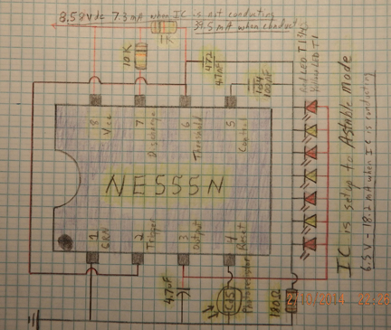
I have found an interesting anomaly with the 555 IC. Everywhere I've read and looked, the #4 (reset) pin has voltage held high to allow the IC to conduct, and then dropped low to turn off (reset) the IC.
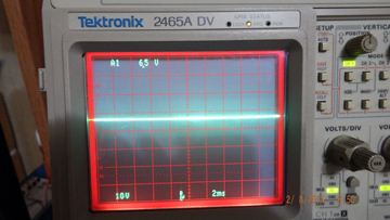
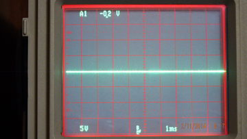
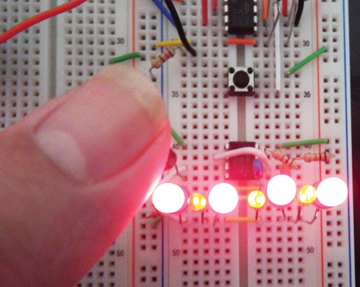
I have 8.58V at 39.5 mA at VCC (#8) pin when the IC conducts. As you can see in the, I am controlling the IC through the reset pin (#4) with a CdS photocell photoresistor. When light is removed from the CdS photocell and the IC conducts, it sends 6.5V at 18.2 mA to the output (#3) pin and LEDs. Apply light to
the CdS photocell and the IC stops conducting; you then get -0.2V at 0.0 mA at the output (#3) pin. Since I added a 4.7 mF electrolytic capacitor to the output pin, the IC now conducts 7V to the LEDs.
I am an electronics hobbyist who has been learning electronics for one year. I welcome any comments and ideas anyone has about what is going on with the IC.
**3/28/14 Update from original question.
I made a mistake on the schematic - the ceramic caps & LED's do not share the same ground line. I also removed the LED resistor and gave them each their own 470ohm resistor to lower the current.
#4141
Robert Calk Jr.
via email
Please log in to post an answer.
Answers
Reader Robert Calk Jr. writes that he has found an interesting anomaly with the NE555 integrated circuit. (IC) Although I cannot answer his specific questions here, I can relate an experience illustrating a similar issue, that I had some years ago when the company I was with was assembling under contract a printed wiring assembly intended for use as a trailer brake controller, by a large well-known company. Thousands of assemblies were involved.
Anyway, the design was theirs, and we as assemblers were required to follow their bill of material exactly. At the heart of the controller was a 555 IC used in generating the pulse width modulated output to the brake "pucks" on the trailer.
To make a long story short, we eventually found out that the designer had unwittingly made use of and designed into his circuit, an undocumented feature or "anomaly" of the particular brand of 555 IC used. I am not sure now, but it may have been a National Semi part. In any case we eventually had supply problems and had to source the 555 from another manufacturer. Guess what, that brand did not work properly in the circuit. Neither did 555's from any other manufacturers!
The lesson here, is that a common industry parametric specification for an IC like the simple 555, or any other for that matter, will likely be closely adhered to by all suppliers of the part. However, the internal circuitry on the chip inside the IC from each supplier, may be quite different from one to another, and may well have characteristics outside of those on the data sheet.
My best advice is to look for and download application notes re the 555, that may be available from some different manufacturers.
Don Dorward
via email
The NE 555 is setup in astable (free-running) mode so it is oscillating. The output signal would be a square wave at the astable frequency. You measured the average DC output as 6.5 volts. Adding the 4.7µF capacitor is a filter to the output, and the new measured DC output is 7 volts.
To verify this, remove the 4.7µF capacitor, and use your oscilloscope to see the waveform at the output. Then reconnect the capacitor and read it again.
Raymond Ramirez
via email
In TechForum "555 Anomaly" Robert Calk, Jr described the strange action of a 555 Astable Mode circuit. First of all the circuit on your diagram is not wired as an Astable Mode 555 device or any other 555 circuit with which I am familiar. There should be a voltage divider from the +Vcc to pins 2/6 and 7 but you have drawn the 10K resistor as an "input" resistor for pin 7 (discharge) and the 1K resistor as an "input" resistor for pins 2 (Trigger) and 6 (Threshold). Pins 2, 6 and 7 have the Vcc voltage applied, NOT the voltages needed to operate the 555's comparators. Plus, the 4.7nF (0.0047 micro-F) and 100nF (0.1 micro-F) capacitors are routed to ground via the 180 ohm resistor (bad practice because any noise on pins 2, 5 and 6 will produce a noise voltage across the 180 ohm resistor which could affect the circuits operation (e.g, false triggering).
I am not sure what you are trying to do with this circuit but it looks like you are trying to turn on the LED's when the CdS photoresistor is covered. The 555 is used for timing, which is not needed in your project, so getting the same result could be easier using a digital logic circuit such as a 7404 hex inverter using the CdS cell to trigger one inverter pin (with pull up resistor to Vcc for light ON when cell uncovered or CdS cell as the pull up resistor for light ON with cell covered).
I think your circuit turns ON the LED's with the CdS cell covered because the extra resistance between pin 4 (Reset) and ground causes pin 4 to go to a "High" via internal connections, thus putting the 555 output in the set or "High" state which powers the LED's.
Get a data sheet for the 555 and see how it should be configured. A good electronics tutorial from the Internet is also advisable.
Tim Brown
Honea Path, SC
Your description of the behavior of your 555 circuit does not suggest anomalies but rather — as an old engineer once told me — "the circuit will always work the way you wire it." The 4.7 µF capacitor across the output terminal is putting an abnormal stress on the pullup circuit within the device. Voltage observed on pin 4 (/RESET ) is normal for open-circuit conditions.
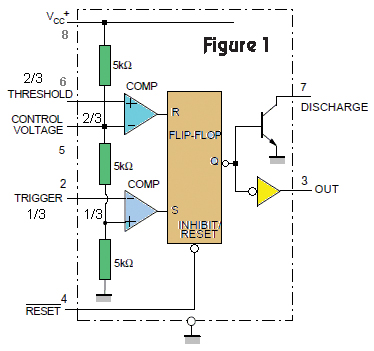
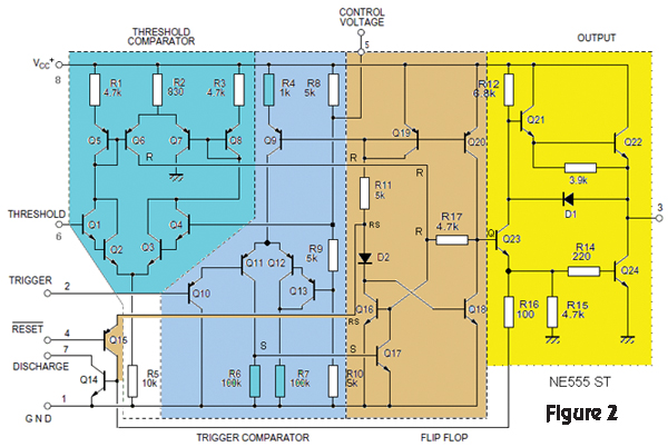
In order to use the 555 effectively, you need to know what's inside the device and how it works. When I design a 555 into a circuit, I always generate a schematic symbol that is more than just a rectangle with eight named pins. Rather, I show what's inside it — an equivalent circuit — because several years later I'll probably not remember exactly how one works and the added detail helps. Figure 1 shows the equivalent circuit of a 555 and Figure 2 shows its internal circuitry. Look at Q21 and Q22 in Figure 2 for some insight into what the 4.7 µF load might be placing on the circuit.
In the equivalent circuit, you'll see that the output is driven by a set/reset (SR) flip-flop which also has an overriding active-low master reset input (that is, you must pull the /RESET input to ground in order to reset the device). The Set (S) and Reset (R) inputs to the flip-flop are driven by comparators which are biased to 2/3 Vcc and 1/3 Vcc, respectively. If Vcc = 12 volts, then 1/3 Vcc = 4 volts and 2/3 Vcc = 8 volts. If the THRESHOLD input is made greater than 2/3 Vcc, the flip-flop will be reset and OUT (pin 3) will fall (to ground). If the TRIGGER input is made less than 1/3 Vcc, the flip-flop will be set and the OUT erminal will rise to Vcc.
In your application, the circuitry controlling the 555 can be simplified. Remove all of the components. Connect pins 2 (TRIGGER) and 6 (THRESHOLD) together. Connect this 2+6 pair through a pullup resistor to Vcc. Connect the 2+6 pair through your CdS photoresistor to ground. Choose the pullup resistor value such that a "dark" condition makes pins 2+6 rise to greater than 2/3 Vcc, and such that the "light" condition makes them fall to less than 1/3 Vcc. If you want the opposite behavior, reverse the circuit. Pull pins 2+6 to ground through the resistor and connect the fixed end of the CdS photoresistor to Vcc.
Finally, I caution you about paralleling LEDs. There is nothing to guarantee that they will all operate at precisely the same terminal voltage. Proper usage dictates that each has its own current-limiting resistor, and then you wire the eight LED+resistor pairs in parallel.
There are many, many articles on the Internet regarding 555 circuits, as well as application notes from Signetics, Phillips, and Texas Instruments. I recommend them to you. Good luck.
Peter A. Goodwin
via email


