The lights on my boat trailer work erratically. Sometimes they work fine (turn signals, brakes, and running lights); other times, when I press the brake pedal, only the right turn light comes on and all the running lights go out! Short of tearing it all out and re-wiring from scratch, any tips on how to locate the fault and fix it?
#8162
Craig Priolo
Saint Louis, MO
Please log in to post an answer.
Answers
Sounds like a grounding problem. Take a jumper cable between the hitch and trailer frame to make sure you have the trailer grounded. If this is a tilt trailer then also jump across the pivot point to make sure all sections of the frame is grounded. Lights work? Then check your ground to car frame on car side of trailer light plug. Check the ground on the trailer side of plug to trailer frame. If it tilts then install a permanent jumper across the pivot. The reason it is intermittent is the ground is only sometimes through the hitch ball. When there is a no ground situation, the lighted bulb is feeding back through the other bulbs positive wiring.
Steve Benson
New Castle, IN
There is not enough information given to arrive at a certain answer, since a lot of necessary information is missing but it looks as if you have a ground problem. On my trailers I have seen the same issues and the culprit was a poor ground connection, raising the ground potential at the offending lights so high, that the running lights turn off when the relatively large brake/turn lights are turned on, assuming the running lights are grounded at the left lights.
Diagnostics is easy, measure the ground potential directly at the offending light bulbs against a known good ground, the trailer connector is best. However, it needs to be said that there are many different wiring schemes such as 4-way, 5-way and 7-way plugs, electric brakes, break-away and other batteries and relays which can cause issues – if need be, you need to measure all signals and draw your own conclusions. To get a good ground, the connections need to be corrosion and oxidation free. You can use dielectric grease to prevent early corrosion.
I have had to run separate heavy ground wires to all consumers in star fashion starting from the plug to fix serious issues. Lights which get their ground connection through their mounting studs and electric brakes with their high current draw are especially troublesome.
Walter Heissenberger
Bennington, NH
I have spent my life fixing the sins of good intentioned people who were in a hurry. First of all, NO, there is no easy fix! But understand the harsh environment, and you can stave off the corrosion gremlins for a good while. Replacing old lights with the new waterproof LED fixtures makes huge sense.
(1) Assume that ALL parts are corroded, and NONE are salvageable. If you won't do this, REMOVE and REWIRE the ground bolt. Grind, file or sand the frame where the new bolt will attach, and GREASE EVERYTHING thoroughly. Use the cheapest tub of wheel bearing grease from the auto parts store, or (better) marine grease for $2 a pound more. Better to run separate ground wires to all lights individually.
(2) GREASE ALL WIRES BEFORE YOU PUT THEM INTO THE CRIMP TERMINALS. Do NOT solder anything that you can crimp. Fill the crimp terminals full of grease before you insert the wire, also. Don't worry, the crimper will expel enough grease to make a good connection. Pull on the finished crimp splice. If it comes apart, learn how to do it right. My all-time favorite crimper is the Dimple-Crimper. I know it is only for bare uninsulated barrels, but it holds the wire better. Feel free to fill a piece of shrink tubing with grease and put it over any splices.
(3) OPEN UP any old splice, as it was likely done poorly. Use a Western Union Splice (soldered) or a new butt-joint connector. TRUST NOTHING!
(4) Sand the bulbs clean, then grease them gently. The grease keeps the corrosion from starting. Clean the sockets, too. Better to replace them. ALL METAL PARTS ARE SUSPECT. Jumper over any rivet from brass piece to brass piece with a short piece of wire.
(5) Remember, I TOLD YOU SO! If this doesn't work, go back and put in all new wiring, but DO IT RIGHT. The fresh or salt water environment is out to get you, and to eat all your stuff. Live with the constant cleaning/greasing/replacing of your equipment, and keep after it! There is NO EXCUSE for losing a brake light!
Hap DeSimone
Santa Barbara, CA
What you describe are classic signs of a bad ground (return) line to your trailer. The quickest way to confirm this is to take a heavy jumper wire and connect it to a clean metal spot on the trailer and the other end to the towing vehicle bumper or frame. (using one line of a battery jumper cable works good for this!) If the lights work normally now, it means the trailer lights were being grounded only through the trailer hitch. Even on the smallest four pin trailer connector, one pin is for the ground connection. It is the white wire on the pin that is opposite of the other three. This is usually corroded and should be cleaned or replaced. I have seen some trailers that do not have this wire connected at all!. Make sure it is actually connected to the frame. Most auto or RV stores have replacement plugs and sockets. The standard four pin wire connector color code is: yellow is left turn, green is right turn, brown is tail lights, and white is ground.
Ron Kmecik
East Springfield, PA
Likely poor ground connections cause the intermittent lamp behavior you observe. A trailer frame provides a poor common ground for lamps. Run a separate ground wire to each lamp socket and join them near the vehicle-to-trailer connection. Then use a single ground wire from that point to the trailer-side connector's ground pin. Also ensure you have a good clean connector. Next, connect the vehicle-side ground wire to a good grounding point on the vehicle's frame. Better yet, run a separate vehicle-side ground back to the battery. Fourteen-gauge stranded wire should work well. Check connections regularly.
Jon Titus
Herriman, UT
No doubt about it, trailer lights are a pain. There are a multitude of possible trouble points.
First of all, if you are launching your boat correctly, then the back end and sometimes the whole thing gets dunked under water. The channels of the trailer frame get filled with water and never really have a chance to fully dry out. Since the channels are steel, they begin to rust. Rust turns clean, shiny ground connections into high-resistance points and strange things begin to happen. The drain holes allow little critters access to the inside of the channels where they set up housekeeping which includes munching on your wires.
The cable feeding the lights from your vehicle gets a lot of flexing and can fail in a whole bunch of ways, especially that flat 4-conductor stuff. The lampholders on the trailer are also prone to failure from the periodic dunkings, even the ones claiming to be sealed.
And do not forget the connectors themselves. The vehicle mounted connector is vulnerable to all kinds of weather conditions 365 days a year which means it is susceptible to oxidation and corrosion.
I have to warn you right now that you have to be careful when working on the vehicle connector, especially if it is the large, round 7 contact type. One of the contacts has full vehicle battery voltage on it continuously, protected by a 30- or 40-amp fuse. If you accidentally short this contact to ground, additional damage can result.
So disconnect the battery first, or at least pull the fuse. Diagnosis: first thing you have to do is isolate whether the problems are vehicle or trailer related. Could be both. The auto parts store will sell you a nifty little tester with several LED’s that you plug into the vehicle. and will indicate whether or not a voltage appears on a specific contact when the corresponding circuit is energized.
These can be useful, but have their limits. An LED is a low-current device compared to the current drawn by your lights. If you have a less-than-perfect connection somewhere in the system the LED will merrily light up indicating everything is wonderful. But substitute a real world load of a few amps and the resistance of the poor connection will drop the available voltage dramatically. Same goes for using your multimeter: the current drawn by the meter is way too low for high resistance connections to have much of an effect. What you can do, however, is connect the trailer to the vehicle, then start checking various points with the meter since the trailer is the real world load condition for the circuit.
Establish a good connection to the vehicle battery negative terminal (assuming a negative ground system) for the minus side of the meter. Then begin checking the various points on the trailer while the lights are energized.
You can also check for crummy ground connections by touching the meter probe to the shell of each lamp. You should read no more than a few millivolts from the shell to ground. Anything greater than a volt is definitely suspect.
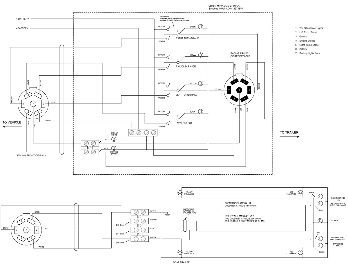
What I ended up doing is building a box that connects between the vehicle and the trailer, with a lamp (incandescent, for the reason cited above) for each circuit so I can see at a glance whether the circuits are getting power from the vehicle or not. The box also allows me to connect a stand-alone battery to the trailer and power each circuit individually for testing purposes. The diagram for it is below, should you be interested. It has saved me lots of time and trouble.
Jerry McCarty
Jackson, MI
Sounds like a classic case of a bad ground. Boat trailers are bad for this type of problem. Most manufacturers use the steel body of the trailer as the ground return to the tow vehicle.
You will need to check the ground connections at each lamp, and at the harness (to the tow vehicle) connection. When you find the bad connection, clean any rust or corrosion off, then use a paste corrosion inhibitor (zinc suspended in a heavy grease such as this: [url=http://sw-em.com/anti_corrosive_paste.htm]http://sw-em.com/anti_corrosive_paste.htm[/url])on the connection before reattaching.
Use an ohmmeter to check lamp to ground (steel chassis) connections, but also don’t forget to check where steel members tie together (if bolted) to ensure the ground passes through.
You may want to run (recommended) a separate ground wire to each lamp, and connect it directly to the cable harness at the hitch.
Ray
Canada
The answer is simple: Fix the grounds. The reason that one light lights is that the one light that lights has the lowest resistance connection to the power source (brake light circuit in the car) and without a secure ground connection, the circuit through the lamp is completed through the filaments of all the other lamps back to ground.
Especially with boat trailers, you cannot rely on the metal frame of the trailer for a secure ground. Corrosion between the steel parts insulates them from each other. Similarly, you cannot rely on the trailer ball providing a good contact to vehicle ground. Therefore, you have to have a good source of ground in the vehicle to the trailer light connector and the connector on the trailer end should be firmly bonded to the trailer frame.
For best results, there should be a ground wire that connects to that same point on the trailer frame going to each light on the trailer.
George Andersen
New Port Richey, FL
Check the grounds first. Often, they use the trailer chassis as ground. When a ground pops loose, bulbs wind up in series that weren’t supposed to be, causing weird symptoms like you describe.
Chip Veres
Miami, FL
This sounds like a bad ground issue, indicated by other lights turning off when one turns on.
ince the frame is likely the common ground and not a separate wire, start with the ground connection where the wiring harness connects to the trailer. Also check the trailer/car connectors grounds. The lights may have a ground wire to the frame, or are grounded by the fixture mounting screws, check those screws, likely rusty.
Since it’s sometimes working, it’s a connection going bad or getting worse. Not surprising, considering they keep getting dunked in water.
Doug Arndt
Chicago, Il
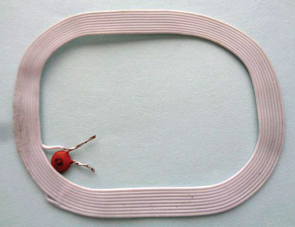
My old billfold was worn out over the years. I planned to retire it when I noticed in back was a coil of 10 revolutions (6 cm x 4.8 cm) with a capacitor marked 47 soldered to the ends, welded in plastic, the size of a credit card. I had never noticed this. Could it be a security feature to prevent devices from getting to my credit card? How would it function? Just curious. A picture of it is shown above.
#8161
Christian Bock
via email
Please log in to post an answer.
Answers
What you have is an LC parallel resonant circuit in which the inductor (L) is a loop antenna similar to the ones found in old AM radios, and 47 picofarad capacitor (C) tuned to resonate at the 13,56 MHz signal frequency used by credit card RFID chip readers. At this resonant frequency, the parallel LC circuit has a very high impedance and effectively absorbs most of the RF energy from a hackers reader to protect the information on your credit card chip. I bought a couple of wallets that protect RFID chips, which have a layer of aluminum foil sandwiched between the layers of leather and cloth in the wallet. It makes a Faraday cage which prevents the hackers RF reader from stealing my card info.
Tim Brown
via email
It looks like you have the remains of a security device that was intended to prevent shoplifting the wallet when it was new. Checkpoint Systems or something like it. Someone forgot to remove it when the wallet was sold?
Chip Veres
Miami, FL
I’m trying to hook up my old Cobra 148 GTL CB radio for a road trip, but I can’t find the antenna for it. My radio has SSB (Single Side Band) and I seem to recall I needed a special antenna to match the radio. Any insight from someone in the know would be appreciated.
#7163
Charles Wallace
Redmon, TX
Please log in to post an answer.
Answers
Whether or not the CB radio has SSB capability or not does not affect the antenna used with the radio. All CB radios designed for use in the USA (assuming unmodified, factory original) operate from 26.965 MHz (ch 1) to 27.405 MHz (ch 40). The antenna must be designed/tuned for this frequency range. There are many choices for mobile CB antennas. A web search will turn up countless suppliers. Determine how you want to mount the antenna (such as mirror bracket, trunk edge, magnetic, bumper) and then look at the length of the antenna you are comfortable using. If the vehicle must fit in a low ceiling garage a long whip antenna may be a problem. Longer antennas will generally outperform stubby compact designs which use coils to load the antenna, although the performance difference is not likely a concern for relatively short range use that would be typical on a road trip. Many CB antennas can be “tuned” so they are optimized at one channel. Your 148GTL has a built in SWR meter for this purpose. For general use, tune for a low SWR on channel 20 (mid point on the CB band).
Erik von Seggern
via email
ANY CB antenna will work. SSB (Single Side Band) operation is merely a mode of the selected channel. AM operation is DSB (Double Side Band, with carrier) while SSB is only -1- side band of the frequency. No special requirements for an antenna. "An antenna is an antenna, is an antenna" is what I have always said. The main differences are, base loaded, center loaded or top loaded. No major difference in any of them if mounted properly and they are of good construction. Avoid nearby metal objects that may 'de-tune' the antenna and affect it's radiation.
Rod Hogg
Scott CIty, KS
I don't believe that side band requires any different antenna, but, if given a choice, I would select a unit with the best gain since side band signals are sometimes weak.
Here is what Advanced Specialties has to say about antennas www.advancedspecialties.net/cb-radio-faq.htm
"WHAT IS THE BEST ANTENNA FOR MY MOBILE CB RADIO?
A - This is tough to answer, & there are many variables, but here are some good general guidelines & "Rules of Thumb" to follow. First, The Taller the antenna, the better it will work. Mount your antenna as high as possible on the vehicle, & try to get at least 50% of it over the roof line. Usually, all else being equal, the Tallest, longest antenna you are comfortable with, mounted as high as possible, will give the best performance. For Example, mounting a new 4 foot CB antenna in the same spot where you were using a 2 foot, will usually give better results. It wouldn't really matter what "brand name", color, or style the 2 ft antenna was. Mounting Height on the vehicle, & the antenna length should be more important than other considerations. Keep in mind that, generally, CB antennas that are less than 3 feet tall, those that "stick to the glass", & the AM/FM/CB "combo" antennas & adapters usually do not give the best performance, they are bought & sold mainly for "convenience" & "cosmetic" reasons"
Len Powell
Finksburg, MD
Yes you do need a special antenna, one designed for CB use. The antenna does not care if you are transmitting AM, SSB, or even FM. That was a trick used years ago, tell people they need a new and “special” antenna for SSB.
It’s like with TV antennas, years ago they sold you special antennas for color and now they sell you special antennas for HD signals. The truth is the antenna does not care what kind of modulation there is, it’s sole purpose is to convert the electromagnetic waves into a usable voltage on the coax/cable. The only thing that does matter is that the antenna is cut to the frequency it is designed to transmit/receive for optimum operation.
Unless you plan to run an illegal amplifier your stock CB antenna will work for you. If you don’t have a wattmeter (swr meter) you may want to see if a friend has one so the antenna can be tuned for maximum output.
Craig Kielhofer
Plainfield, IL
First let me say that no matter how the signal is encoded, the antenna stays the same. The radio waves have not changed, only how we encode the information has changed and this does not affect or change the type of antenna needed to receive the radio waves upon which the information is encoded.
So, the bottom line is that you do NOT need a special antenna for the radio simply because it is using SSB as well as AM modulation. In fact, SSB is exactly the same as AM except that the carrier and one side band are suppressed. So you’re using less bandwidth, and about 2/3rd of the energy that was going into the other side band and the carrier are now able to go into the one remaining side band, thus increasing the distance you may be received.
You are still limited to 4W of output RF energy to the antenna, so the antenna doesn’t need to handle more power, it is not handling different RF frequencies, so the bottom line is that nothing has changed as far as RF and power are concerned.
I will say that if you want to use it mobile and have the best range possible you should use a full 9 foot long quarter wave antenna as we used to use back in the 60’s when I got started in CB. I hope that helps.
Phil Karras, KE3FL
Mount Airy, MD
Any CB antenna will work.
Chip Veres
Miami, FL
Antennas are frequency specific, not mode specific. Any properly tuned CB antenna will work fine, regardless of whatever urban legend you might have heard.
Rick Hadley
Vinton, IA
How do I test/tell the phase of my speakers so I know I am installing the leads correctly?
#7162
Bill Gleaves
El Segundo, CA
Please log in to post an answer.
Answers
Phase a speaker by using a 1.5V D-cell and attach to the speaker leads. Upon connection, the speaker diaphram will move out or in. With the cone out mark the positive battery connection as plus and the negative minus. This way the speakers will move in tandom when recieving the same signal. All very simple, as you want to move the air piston of the speaker to be optimized for volume.
I remember when my Dad built a Knight stereo tube amp in 1960 and made his own BIG speaker enclosures, he explained to me (I was 6 and had just been given my first slide rule and a small sipson VOM) what he was doing while he wired the speakers, he had just graduated from SMU with a BSEE and I absorbed electronics by osmosis.
Bill Ackley
San Antonio, TX
I use a 1 ½ volt battery D, C, AA, AAA. Whatever battery is close at hand. Connect the battery across the speaker leads and observe which way the speaker cone moves (in or out) depending on the battery polarity. Make sure all speakers move the same way using the same battery polarity. Phase is only critical on lower frequencies so it is not really a factor on high frequency tweeters where you might have difficulty observing the speaker movement.
Roger May
via email
I assume your speakers are not in enclosures that have color-coded (usually black and red) connectors. To phase speakers from their frame mounted terminal connections, use a 1.5 volt battery (an AA cell, for example). Momentarily touch the battery terminals to the speaker terminals using whatever jumper leads you have available, and watch how the speaker cone deflects. It will move either inward or outward when the battery terminals are touched to the speaker terminals. Mark the speaker terminal that is connected to the battery's + terminal with a marking pen. Then check all your other speakers the same way, connecting the battery polarity to the speaker so that the cone movement is the same as for the first speaker, and again mark the speaker terminal that is connected to the battery's + terminal.
Bob Stewart
Mancos, CO
Simplest way to determine phase is the old VOM 'bump' test. Using an analog VOM on the low ohms scale, 'bump' or tap the speaker terminals or wires with leads, and see or feel which way the cone is moving. (Make sure your VOM has positive voltage on the Red lead, a few do not) Moving out is proper phase with positive voltage to the + terminal. A modern digital VOM/Multimeter usually does not have enough available current to make the test, so you can just use a "C" or "AA" cell battery. Observing + terminal to the speaker lead marked as such. DO NOT use any higher voltage as speaker will draw excessive current and may be damaged.
Have used this method for 50 or more years, works!
Rod Hogg
Scott CIty, KS
If you are replacing drivers in a speaker, the positive terminal is usually marked with a plus sign or red mark. If it’s a woofer or midrange and there are no markings, connect a 1.5 volt battery to the terminals and note whether the cone moves in or out. If it moves outward, the positive battery terminal is connected to the positive terminal of the speaker; if inward, the NEGATIVE battery terminal is connected to the POSITIVE speaker terminal. If it’s an unmarked tweeter, I don’t think you’d see any motion, but I’ve never tried.
Keep in mind that some speaker manufacturers sometimes wire some drivers out of phase (with the other drivers in the cabinet, that is—both speakers should be in phase with each other) as part of their crossover design. If uncertain, contact the manufacturer for phasing specs.
Alan Rauchwerger
via email
To test the phase of a speaker disconnect the speaker from any external devices (amplifier, crossover, etc) then momentarily connect an AA battery (1.5 volts) to the speaker terminals. If the cone moves outward (away from the magnet) note the polarity on the battery and mark the speaker terminals the same. If the cone moves inward (towards the magnet) reverse the battery connection. With the polarity of the speaker known, make all additional connections to the amplifier, crossover, etc following the same polarity. This test only works on cone style speakers. Do not try this on special types like ribbon speakers or delicate tweeters.
Erik von Seggern
via email
The phase can be easily checked with no test equipment. Switch your amplifier to mono to feed the same signal to both speakers and place the speakers face to face leaving only a small air gap between the grills. If the speaker wires are connected properly, both speaker cones will be moving out/together at the same time, pushing a large volume of air out the gap and producing a loud sound. Reversing the leads on one speaker will cause one speaker to move in while the other is moving out, thereby moving little air out the gap resulting in a much softer sound and revealing the improper connection. Lower frequencies work best for the test.
Dale Carlsen
via email
Put the speakers right next to each other and play something with a lot of bass. Switch the wires on one of the speakers back and forth. Whichever wiring gives the loudest bass is correct.
Bryan Suits
Houghton, MI
Proper polarity is when all the cones of the speakers, move in the same direction, when the same polarity DC voltage is applied to two or more speakers. Stereo speaker terminals are usually marked Red(+) and Black(-), so you just need to keep them mated to the amplifier's terminal markings. If there are no marked terminals, or you just want to verify the polarity, it is easy. If you can see the speaker cone connect a 1.5V battery to the speaker wires so that the cone moves outward when the battery is applied, reversing the battery if the cone moves inward. When the cone moves outward, the positive side of the battery, is the red (+) speaker lead, and the negative is the black(-) lead.
Another method is to connect the speakers to a monaural audio system, and have it play a male voice speaking. When you are centered in front of the speakers, the voice will appear to be coming from between the speakers when the polarity is correct. This also works on a stereo system by selecting the MONO mode.
In any case, if the polarity is incorrect, just reverse the wires at one speaker, or one speaker output at the amplifier. This is most important whenever a group of speakers are in the same area or dropouts and cancellations may result in poor audio. With separated speakers, for example in different classrooms, the polarity usually is not as important since there is little speaker interaction, but good installation practice would be to keep it uniform. As a general rule, mixed polarity of speakers will cause no equipment damage, but can result in poor audio quality.
Len
via email
Most bare speakers have + and - markings on their solder lugs/terminals. As a rule of thumb, connect your positive (usually RED) wire to the + terminal and the negative (usually BLACK) wire to the - terminal. For bare speakers that have un-marked terminals, briefly connect an AA (penlight) cell to the terminals and observe which way the cone moves: if the cone moves out, the terminal the + lead of the battery is connected to is the speaker's + terminal; if the cone moves in, the - lead of the battery is connected to the speaker's + terminal.
For assembled speakers (i.e., bookshelf types), the RED connection terminal is considered the + terminal. Be aware that some speakers simply have un-marked screw terminals. You can check/verify the polarity using the penlight cell test above (make sure you can observe the motion of the main speaker's cone). If necessary, (re)label the terminals to match the test results.
Finally, when connecting your amplifier to the speakers, always follow a common convention regarding speaker wire connections. With all standard twin-lead speaker wires, one lead has a colored stripe (or similar marking) or a molded ridge on the insulation to denote the - output terminal of the amplifier/speaker. By connecting the marked lead to the - amplifier/speaker terminals and the un-marked lead to the amplifier/speaker + terminals for all channels of your amplifier, you'll guarantee proper phasing of all your speakers (i.e., all the cones will move in the same direction with the signals).
Hope this helps and answers your question.
Ken Simmons
Auburn, WA
The quickest way, if you can visually see the speaker, is to see if there are any markings on the solder lugs. In the absence of that, you will need a 1.5 volt battery and a 100 ohm resistor to limit current. If there are markings (assuming the same make/model) then go by those if not you need the battery method.
Attach the minus lead of the battery to one of the lugs, touch the plus side of the battery thru the resistor to the other lug and watch which way the cone moves. There are those that say to mark the lugs + and - when the cone moves in, others say the opposite. The crucial thing to remember is to be consistent. Once you have the lugs identified, the ideal way is to connect + on the amp to + on the speaker.
Craig Kielhofer
Plainfield, IL
Briefly connect the terminals of your speaker to a 1.5V battery. If the speaker cone moves out, label the terminals + & - to correspond to the polarity of the battery. Do this with all your speakers and connect them with the +’s & -’s together. You could insert a resistor (2.2K or whatever you have handy) in the battery lead if you feel it necessary. Usually all it takes is a short tap to determine the direction of the cone movement. Many speakers terminals are marked with the polarity.
Gene Sellier
Fairhope AL
Momentarily connect a 1.5 volt flashlight battery to the speaker. When the positive terminal of the battery is connected to the positive terminal of the speaker, the speaker cone will move toward the listener.
Chip Veres
Miami, FL
Speaker phase can easily be determined by a 9 volt battery and direct connection to speaker leads at the speaker itself, not any equalizing circuits, the connection must be on the speaker!
Briefly touch each speaker lead to the battery. Watch carefully which direction the speaker cone moves. + battery & cone moves out gives the positive speaker terminal. You can do this with most speakers as long as the voice coil doesn’t get too much current too long. A brief touch of battery gives you the answer.
Jack McMahon
Palm Springs, CA
For convention sake, lets say you have speaker wire connected to your speakers. Usually there is one conductor that has a copper colored wire that you would normally connect to the speaker + or Red binding post. The silver colored wire to the - or black binding post.
An old trick - At the amplifier end of the wire, if you connect a 1.5 volt battery positive to the copper colored wire, and the battery negative to the silver colored wire, you should observe the speaker cone moving in or out. if the speaker cones are both moving the same direction, they are in phase and should be connected that way to the amplifier.
Jack Hammer
Wantagh, NY
You can determine the polarity of any speaker with a 9 volt battery. Put the positive terminal of the battery on one of the leads and the negative terminal on the other lead. If the speaker pushes out the polarity is correct. If it pulls in then it is reversed. DO NOT HOLD THE BATTERY ON THE LEADS MORE THAN IT TAKES TO DETERMINE THE POLARITY.
This test should be just a touch-and-go test. The coil in the speaker does not like DC voltage. The easy way to remember this is you want your sound to radiate out not suck in..
Thomas McCraig
Virginia Beach, VA
Useing an “AA” or “AAA” cell, connect one lead (say the negative lead) to one speaker terminal, and touch the positive lead to the other terminal. If the cone moved out, mark that terminal positive and do the same to the rest of your speakers.
I’m not sure that the cone moving out really proves that the terminal is the “positive” terminal, but as long as all your speaker’s terminals are identified the same way, they will be in phase.
Jerry Ryba
Long Island, NY
Very simple: connect a 1.5 Volt battery (AA or AAA) to the speaker leads while noting if the speaker diaphram moves inward or outward. Then, mark the leads as + and - according to the battery poles when the diaphrams move in the same direction. If you cannot see the diaphram movement, lightly stretch some thin celophane food wrap in front of the speaker, making the wrap as air tight as possible, then watch to see of the celophane bulges outward or “sucks” against the speaker front.
Donnie Agema
Hattersheim/Germany
Easiest way is with a 1.5V battery and a pair of test clips. Do not leave battery connected for any length of time.
Connect one of the leads to the speaker terminal and one of the battery terminals. Then touch the other speaker terminal to the remaining battery terminal briefly while observing the direction the speaker cone moves. Mark the battery polarity on the speaker near the terminals. It should move either in or out. Do the same test on the other speaker swapping battery polarity if needed until you get the same direction of movement.
I tried this test using a digital ohmmeter but the current was to limited. An analog VOM on the RX1 or RX10 range is an alternative testing source.
George Shaiffer
Colorado Springs, CO
Connect a 1.5 volt battery through a 10 ohm (or there about) resistor to the speaker terminals and observe the direction of the cone movement. Generally, connecting the positive terminal (usually marked with a red dot) to the positive battery connection will cause the cone to move outward. Test both speakers and mark the terminals. go make some noise.
Chris Snyder
Cosby, TN
One way to determine the polarity of a speaker is to use a battery like a single AA. You need to remove a cover so you can see the front or the back of the speaker and connect the battery to the it. The wire on the flat bottom of the battery is -(negative) and the lead connected to small protrusion is the +(positive)
When you connect the battery to the speaker, for an instant the speaker cone will move. Make a note of which way it moves and mark the speaker terminal +. Connect the same battery leads to the next speaker connections and note the direction the cone moved. If it moved the same way mark that speaker terminal +. If it moves the other way, in or out, but different than the first speaker, reverse the battery connections and when the speaker moves the same way as the first mark a + on the terminal with the + from the battery. Once all the speakers are marked, you know the phase.
Ned Stevens
Saint George, UT
My vintage JAX “fuzz” guitar pedal (Figure 1) seems to be dead. I’ve put a new battery in it but it doesn’t pass sound at all – even when I press the bypass switch.
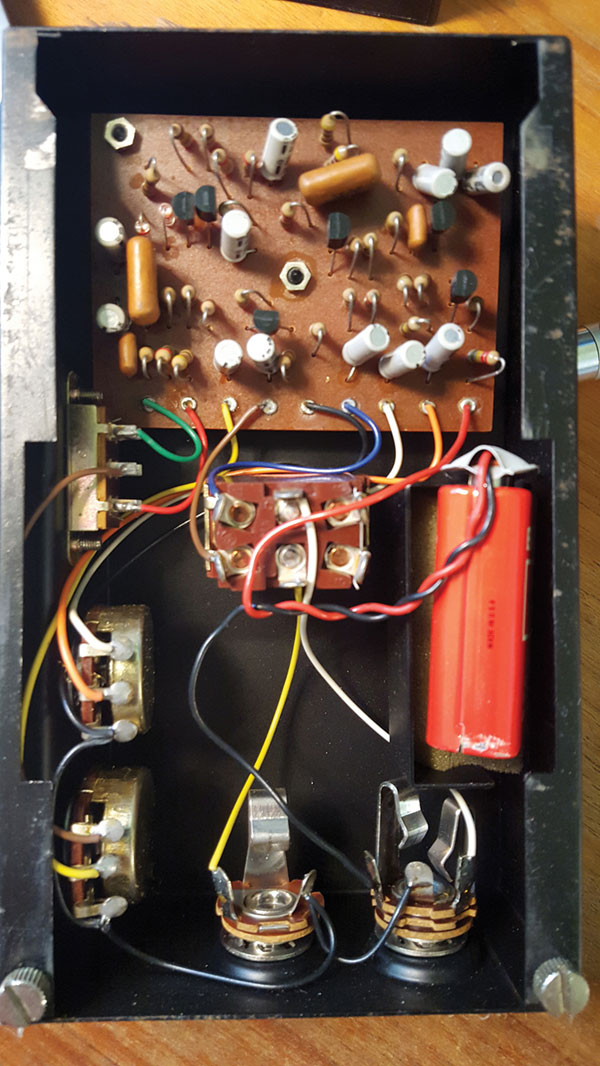
FIGURE 1.
Luckily, the schematic (Figure 2) is printed on the inside cover. I would greatly appreciate suggestions on where to start figuring out what’s wrong.
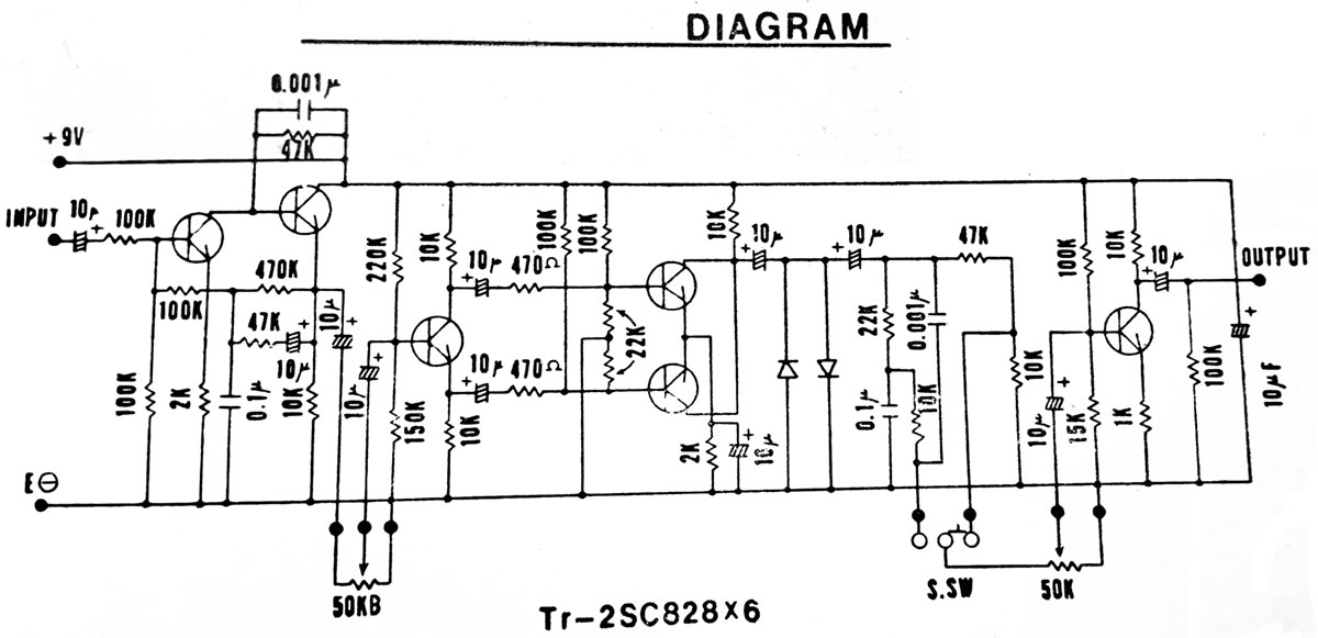
FIGURE 2.
#7161
Jesse Ortiz
Downers Grove, IL
Please log in to post an answer.
Answers
The schematic is unnecessary for fixing this problem. Looking at the picture, the wiring of the second switch in the photo tells the whole story. There are only 5 components involved in bypass mode: 2 guitar cords, 2 jacks, and one DPDT switch, plus the wiring. If it were a broken wire you would see it.
First, check both guitar cords by plugging the guitar directly into the amp or doing a continuity check. If one or both are bad, you’re done. If not, remove the battery, plug a cord into each jack, and check continuity from the sleeve of each plug to the sleeve contact on its jack (note that on the right hand jack in the photo, you want the shorter sleeve contact. The longer one controls battery power); repeat from tip to tip contact, if needed. Bad continuity means a bad jack, since you know the cords are good. If all else shows good continuity, the switch is bad.
Alan Rauchwerger
via email
I would start by replacing all the 10 µF electrolytic capacitors (the gray components standing up with 2 leads exiting the bottom). Electrolytic capacitors age, and in the absence of electric charge can eventually short or develop a high internal resistance. Perhaps only one is defective, but likely all are marginal and others might fail in the future. It's easier and cheaper to replace them all than to attempt using an ohm meter to determine which are good and bad. Jameco P/N 29891 is a suitable replacement part that costs $0.15 each ($1.80 for the 12 you'll need). RadioShack has a suitable part also (2721025), but its price is $1.49 each. Use caution removing and soldering in the new parts. The old single sided PCBs have copper traces that de-laminate easily with heat.
Bob Stewart
Mancos, CO
As the fuzz pedal is pretty old, I would suspect a defective capacitor, the electrolytics, 10 µF, is the problem. Looks like the unit has 12 of the caps, and as inexpensive as they are I would just change them all out as you have to take the board out even even to change one. That era of caps tend to 'dry' up or even sometimes go 'short'. Even if they are not totally defective, I am sure new ones will make a marked improvement of operation.
Rod Hogg
Scott CIty, KS
I suspect your DPDT bypass/operate switch is bad. With the battery disconnected, the instrument and amp connected, use a very short jumper wire (perhaps with small alligator clips on each end of the wire) to short out the middle two lugs of the switch shown in your Figure 2. Activate the instrument and see if your audio gets into the amplifier. If it does, your bypass switch should be replaced. If this doesn't help you, try replacing your instrument and amplifier cables from the device with known good cables.
Rick Herndon
Austin, TX
The foot switch is not shown in the schematic. Looking closely at figure 1, it appears that the foot switch is simply bypassing all of the circuitry and connecting the input jack to the output jack. Based on your statement, first I would check the cables, then I would check the foot switch.
FYI, while not shown in the schematic, it appears that the power to the circuit is only applied to the circuit when there is a cable plugged into the jack on the right. The barrel of the plug shorts the ring contact to the barrel thereby connecting the battery “-” to the circuit ground. Good luck.
Jack Hammer
Wantagh, NY
Most of those old pedals, and even the new ones, used the case as ground. If the jack nut is not tight or if there is corrosion on the jacks they will not work right. The first thing I check when I get one of these in is the jack nut. That usually fixes the problem.
Thomas McCraig
Virginia Beach, VA
I studied the schematic you provided on the Vintage Fuzz and found that the schematic is not complete. It does not show the bypass switch or how power actually gets applied to the amplifier.
From the picture, it is apparent that the amplifier only receives power when a mono phono plug is plugged into the jack directly below the battery. Please verify that the phono jack you are using is mono, not stereo. It appears that the switch located on the top center of the enclosure is the bypass switch. If I am correct, then it stands to reason that your problem is caused by a stereo phono jack because the center connections on the bypass switch are tied to the input and output phone jacks and completely bypass the electronics, but a long phono plug must be used in both jacks for the signal to pass from input to output. Note that the tip on the phono plug carries the signal and the middle contact on the phono jack below the battery provides power to the amplifier through the ground (barrel) of the mono phono plug.
If a stereo phono plug is used no power will be supplied to the amplifier. This same problem would occur if you have used a stereo phono plug to RCA jacks or some other connector and accidentally chose the wrong stereo channel because no audio signal connection exists on the middle ring of stereo plugs when plugged into this fuzz box.
Ronald Gladney
Soddy Daisy, TN
Assuming you have proved you have an output from the guitar, also the amplifier and both cables are OK, the fault must be either the FUZZ boxes bypass switch is faulty or a break in the internal wiring between the switch and one or both 1/4” jack sockets.
A quick continuity test with a multimeter will prove where the fault is.
John Swift
via email
I have a very attentive dog who barks immediately when someone is in the backyard or at the front door. This is great for alerting me to visitors or possible intruders, but I really can’t hear as well as I used to and my dog has a rather quiet and high-pitched bark that I mostly can’t hear — especially if the TV is loud. I would like plans or a design for a “dog bark detector” to blink a light by my chair when the dog is barking so I don’t miss these “alerts.” Does anyone have a circuit or schematic for such a thing?
#6165
Irvin Lynch
Columbia, MO
Please log in to post an answer.
Answers
You don't need to build hardware. You already have all the “hardware” you need. You need to do some programming; namely, programming (teaching) your dog to push on your hand when there is an intruder. Such a trained dog is known as a service hearing dog or signal dog. Find a skilled trainer to teach your dog to alert you by physically pushing on your hand or if your dog is tiny to whack your ankle.
A trained dog is infinitely more useful than any circuit you can build, e.g., when trained to do so the dog will wake you up when the alarm clock goes off, keep you from being run over by cars and bicycles, tell you when people are sneaking up behind you or are at the front door. A dog will alert you to anything you teach her. The idea here as in most engineering problems is to solve the problem at hand in the simplest way rather than forcing a preconceived and quite possibly inferior notion to do what you want.
Bruce Hartenbaum
via email
Does anyone have a schematic for a pinewood derby finish line race timer? I would prefer to build something that doesn’t use a microcontroller, if at all possible.
#6164
Kirk Bateman
Minneapolis, MN
Please log in to post an answer.
Answers

When my grandchildren were into Pinewood Derby racing, I built a “which came first” circuit. The system has two 12 volt lamps mounted above the track at the end. The car that breaks the beam causes the lamp to light and locks out the other track. A tie is not possible.
A 12 volt, center tapped transformer supplies 5 VDC to the logic and 12 VAC to the lamps. The logic consists of nand gates and set-reset flipflops. When one FF is set, it energizes a relay that lights the lamp and simultaneously locks out the other channel.
A 38 or 40 khz IR transmitter is mounted above the track at the end and the receiver is mounted under the track (or vice versa). You may be able to find a receiver at RadioShack, Ebay, or Amazon. The receiver is 38khz but 40khz will work fine. I used reed relays that will work on 5 volts but any 5 volt relay will work. My original system included a three digit timer but 8 to 10 year olds are not interested in the time.
Russell Kincaid
Milford, NH
I inherited an antique “cat’s whisker” crystal radio set. Everything seems to be intact except the actual crystal that the cat’s whisker touches. Any ideas on where I can find a replacement crystal?
#6163
Jeffery Payne
Newport News, VA
Please log in to post an answer.
Answers
As a boy, I used a piece of “galena” from my rock hound father's rock collection. Ask around for companies that cater to this hobby. I also experimented with making my own crystals. Get an old fashioned 100% copper penny or go to a hobby store and get a strip of copper. You need to get the penny (copper) perfectly clean. Put 1 tsp (5 g) of salt into 1/4 c (2 oz) of vinegar (or lemon juice). Soak the penny for 5 to 30 minuets. Wash the penny well with plain water.
Heat the penny from the backside using a small torch, or the flame of a gas stove, or laying it on the red-hot burner of an electric stove. When the penny develops a reddish sheen (cuprous oxide), remove it from the flame and it is ready to use. Clean a small spot on the edge of the penny with a piece of sandpaper and connect it to your crystal radio. Then use the crystal radio’s cat whisker to probe the reddish area to look for a hot spot.
You can also cheat (not an option when I was a young boy) and use a small signal diode like a 1N34 or similar.
The REAL secret to a crystal radio is to use a set of high impedance earphones. Today’s earphones are mostly all low impedance and will not work unless you use an audio impedance matching transformer between the crystal radio and the earphones.
Jerry Navratil
via email
The crystal most often used for old-time cat's whisker crystal radios is a naturally occurring mineral, galena, which is an ore of lead (lead sulfide). Galena is a naturally occurring semiconductor. The point contact of the whisker (a piece of wire) and the mineral form a rectifying junction. You can find samples of galena at many tourist gift shops, some museum gift shops, as well as from some online sources. It is a shiny black mineral and a small piece should not be very expensive.
According to my father, who used to play with cat's whisker radios when he was young, making a good rectifying contact takes considerable patience and the contact will age and so will need to be redone every now and then. More reliably, but with less historical accuracy, you can replace the whisker/galena portion of the radio with a small-signal semiconductor diode, which is what I did when I was young. A germanium diode, such as a 1N34, is usually better for this than a silicon diode, due to the lower turn-on voltage of germanium.
Bryan Suits
Houghton, MI
First off, the crystal in a crystal radio was made from "galena," but if I remember correctly, you could also make this work with two pieces of dissimilar metal or a modern diode. The way these were made originally was with a pin and a rusty shaver blade; the pin touching the blade made a crude diode, which rectified the signal on the RF carrier. The rust was very important, it was what helped make the crude diode. Pencil lead was better to use instead of a pin because further rusting would ruin the diode effect and lead won't cause further rusting/oxidizing. The thing wanted is two dissimilar metals so that there is a charge gradient, the thing that causes dissimilar metals when touching to oxidize. Most touching dissimilar metals, if picked correctly, will act as a sacrificial anode. In other words, it acts as a diode. A diode that could be used is the 1N34. see: www.techlib.com/electronics/crystal.html
Here's another really good article: https://en.wikipedia.org/wiki/Crystal_radio and I quote, "It gets its name from its most important component, known as a crystal detector, originally made from a piece of crystalline mineral such as galena.[1] This component is now called a diode." and "The lead point touching the semiconducting oxide coating (rust) on the blade formed a crude point-contact diode." and " The lead of the pencil is made of graphite and clay and so it would inhibit further corrosion that would result if copper or iron wire was used in its place."
Philip Karras
via email
You can find replacement cat-whisker/crystal assemblies on eBay, but they're quite expensive. A simpler solution is to replace the cat-whisker/crystal assembly with a germanium signal diode — 1N270 or 1N34. Identify the non-banded (anode) end of the device case and connect it to the cat-whisker holder. The banded (cathode) end connects to the crystal cup holder.
Peter Goodwin
Rockport, MA
You need what is known as a Galena crystal. You can find these on eBay, etsy, and similar websites. I found several listings under $10. If you need the entire detector including the stand and adjustable wire, google "cat's whisker detector".
These detectors were in use at the very beginning of the last century, before vacuum tube detectors were available. They create a semiconductor diode, using a fine wire (the "whisker") just touching the Galena Crystal. Getting them to work was and is something of a black art because not all areas of the crystal will act as a diode when touched by the wire, and they are sensitive to pressure, movement, and vibration. If you want to play with the radio receiver without having to adjust the crystal every time, you can replace it with a 1N34A germanium detector diode. These are available on eBay and also at any electronic component distributor for a couple of dollars.
Mark Lewus
Denville, NJ
You need a small piece of the mineral galena (lead sulfide), although some crystal radios use pyrite (iron sulfide), also known as Fool's Gold because of its color. Borden Radio Company sells galena crystals for $5.00. www.xtalman.com/detectors
Jon Titus
Herriman, UT
The most common mineral used for cat’s whisker detectors is Galena (Lead(II) Sulfide). This is readily available from mineral/fossil collection suppliers and many hobby stores. It’s cheap and you only need a tiny piece. Some museum shops and toy stores also sell it but you may have to buy a collection. It can also be found on on-line auction sites. G8RPI.
Robert Atkinson
Cambridge, UK
I searched the internet for "crystal radio" and got millions of hits, including Amazon.com. Just search.
E. Paul Alciatore III
Beaumont, TX
You can replace the cat’s whisker and lead galena crystal with a 1N34 diode; but if you want the real thing there are two choices:
- Go to www.minerals.net/mineral/galena.aspx which will give you locations in the USA where you can get crystals yourself.
- Go to eBay and search for lead galena crystal. Most of the listings are pricey but I found some for about $8 from England, including shipping. A rock shop in Galena, Ill should sell a small crystal for a reasonable price.
Russell Kincaid
Milford, NH
The crystal is galena or lead sulfide. The crystals may be found on ebay or other gem sites. My crystal was embedded in lead with at least half showing. It's tricky to get a good spot. Happy gem hunting!
Al
Needham, MA
The crystals used were small chunks of galena (or pyrite, i.e., “Fool’s Gold,” I believe?). Because the “atomic structures” of the crystals used were, at best, iffy, it took a lot of practice to find the right spot(s) on the crystal that would give a strong, usable signal. You can get some galena and/or pyrite at any rock shop. Just make sure you don’t get any polished crystals — you want the surface to be as raw as possible, but make sure it’s clean.
Ken Simmons
Auburn
Building crystal radio sets (of wide variety) was one of my hobbies for years. I would suggest keeping it authentic by making your own replacement. This is not difficult. Here is a great source of information: http://bizarrelabs.com/crystal.htm There is much more information to be found. Crystal radios still have quite a following!
John Sinks
Edelstein, Ill
Could someone please tell me if the ESP8266.01 module is compatible with the Raspberry Pi? And/or where can I find a Wi-Fi and GPS module that are?
#6162
Timothy Harner
via email
Please log in to post an answer.
Answers
There is an instructable on how to use the ESP8266 with the Raspberry Pi at www.instructables.com/id/Connect-an-ESP8266. However, I don't recommend that you use it because it communicates over the hardware UART. This will result in an extremely slow 115kbps Internet connection, about 1/100th of the speed of a typical 10mbps cable system connection. It will also tie up the UART which you will need for the GPS.
If you have a Raspberry Pi model 3, you do not need to add a Wi-Fi adapter at all since one is already built into the board. Use a version of Raspbian dated March 2016 or later to avoid driver issues. For older boards the simplest solution for Wi-fi is to use a small USB adapter. I have had success with the Edimax EW-7811Un, available from Amazon and others for $9. It supports 802.11b/g/n up to 150mbps and it's supported by any recent version of Raspbian.
GPS is also straightforward. Most receivers use a simple async serial port and are pre-configured to transfer data at 4800 bps, no parity, 8 data bits, 1 stop bit though this can be overridden in software. Data is transferred using the NMEA (National Marine Electronics Association) protocol. Google "GPS protocol specification" for information about this text-only protocol made up of 'sentences' that are easily parsed to get time and location information. If you are technically adept you can get a ublox NEO-6M or similar 3.3 volt serial GPS module for around $15 from eBay or Amazon and wire it to the serial port. Using the 26/40 pin I/O connector port, 3.3V power is on pin 1, ground on pin 6, Tx on pin 8, and Rx on pin 10.
A more expensive, but beginner-friendly solution, is to use an extender board known as a HAT that requires no hardware interfacing. One such HAT is the "Adafruit Ultimate GPS HAT for the Raspberry Pi", adafruit.com product #2324. This board includes a GPS receiver, internal antenna, Real Time Clock (RTC), and a holder for a CR1220 RTC backup battery. It also has a U.FL connector for an optional external antenna. This will only work with an original or model 2 Pi as changes to the hardware in the model 3 has made it incompatible with this HAT, at least for now. The original Pi and model 2 Pi work fine. This limitation likely exists with other GPS HATs. If you have a model 3 make sure the GPS HAT mfg. specifically claims support for it before you buy.
Mark Lewus
Denville, NJ
My pool bot timer quit. The transformer is good but the timer is not. I would like to build a timer to switch a relay off and back on every 15 seconds and/or 30 seconds.
#6161
Terry Arnall
Hayward, CA
Please log in to post an answer.