I’m an avid VHF/UHF listener, and have always used a vertical non-directional antenna for receiving signals. However, after buying a circular polarizing filter for my Nikon, I realized that RF can be circularly polarized as well. How can I tell whether a signal is vertically or circularly polarized, without investing in a circular antenna? Do you know of any resources for how to construct circular polarized antennas?
#10171
Ed Moreno
Schaumburg, IN
Please log in to post an answer.
Answers
Circularly or elliptically polarized antennas are used to transmit to both vertically or horizontally polarized antennas to reduce flutter to or from a moving receiver, as mentioned by Don Pitchford. I've seen some local HDTV stations in the Washington D.C. area are now using elliptically polarized antennas and I've found I can receive these stations using either a horizontal or vertical antenna. So, in a moving car receiving the TV signal using a vertical antenna will work just fine. After all, it is much easier to install a vertical antenna on a car than a horizontal antenna is.
There is probably no need for you to install a circularly polarized antenna to receive circularly polarized signals, use either your vertical or a horizontal antenna, either should work just fine.
Phil Karras, KE3FL
Mount Airy, MD
You are very unlikely to encounter circularly polarized radio signals from local sources. Circular polarization is mostly used for receiving Low Earth Orbiting (LEO) satellites and stuff in the microwave and upper end of the UHF ranges. If you do find any of these signals they will have a distinctive rhythmic change in signal strength as the polarization of the signal changes; maximum as it matches your receiving antenna’s polarization, then minimum as it becomes opposite your antenna’s polarization.
If you have a receiver capable of covering the 145 MHz and 437 MHz ranges you may want to check out ham radio satellite sources such as https://www.amsat.org/fm-satellite-frequency-summary for information about receiving them.
As for receiving circularly polarized signals should you find any, if they are strong enough that the null in signal strength is still strong enough for you to hear it clearly, then you will likely not know the signal is circularly polarized and need do nothing special to receive it. For weak signals you will need to try both Right Hand and Left Hand circular polarization to determine which is needed, as the wrong circular polarization is worse than just using a linear polarized (in your case vertical) antenna.
If you want to learn more about circular polarized antennas https://www.e-education.psu.edu/geog862/node/1782 and https://rcexplorer.se/projects/2011/08/circular-polarization-explained have very good simple explanations of what is going on with circular polarization.
The source I recommend for anyone learning about antennas is The ARRL Antenna Book. They are currently selling the 23rd edition, but any edition from the last 30 years or so will likely suffice. Old and new versions are usually available at local ham radio gatherings such as a “hamfest” or online at Amazon.com
Don Pitchford
Springfield, IL
I’m trying to make sense of everything coiled, but the only thing getting wound up is me! I thought I knew a bit about electromagnetics, but recently I’ve been trying to make sense of all these fields and flows.
What is the difference between the magnetic field and the flux? How does flux work in a transformer or a generator? Does anyone really understand Maxwell’s Equations?
So many textbooks dealing with electromagnetism speak in equations instead of English. I want to know HOW it all works, not just how to compute these things. Am I just reading the wrong books? Can you help me figure out what the flux is going on?
#9172
Taylor Street
Felton, CA
Please log in to post an answer.
Answers
I have spent a lot of my life wondering about magnetics. Welcome to the club! Hopefully the information that I have is correct
Here are a few basics:
1. When an electron moves, it generates a magnetic field in addition to the electric field that's always there. — Why?: Because
2.The field exists if the electron/electrons move in a wire, a stream (e.g. in a tube), or anything else.
3. Magnets 'work' because (if I have this right), the arrangement of their molecules is such that the electron orbits of the individual atoms are oriented such that the fields generated add together. The relative strength of a magnetic material is based on how well they are aligned. Magnet discussion usually describes magnetic domains within the material. (Magnetizing a material means that you apply a magnetic field to align the domains.)
4. Non magnetic materials don't feature this alignment. Electron orbits are in random orientation and the fields cancel.
5. Magnetic fields are constant for DC current and non moving magnets.
6. Time varying fields are generated from AC current and moving magnets.
7. Time varying fields do the following: A. If they pass through a wire they will cause the electrons to move — thus a transformer. B. If they encounter another magnetic field they will cause either an attractive or repulsive force — thus a motor. (This force is also present in static field interactions, but that won't make a motor.)
8. Coils of wire are used in transformers and motors because the fields add and compact devices can be made.
9. The field descriptions are always confusing. What I got out of it was that the B field is the description for the field you would find due to the current or magnetic material. The resultant field that you can measure depends on the material that the field is in.
Exmple: If you have a long solenoid, the field inside will be fairly constant if you're not too close to the ends. If you put a piece of ferrous material inside, there will be an increased field through the metal because it's easier for the 'flux' to go through this material. (This also affects the input current to some extent, in the same way that a a lower resistance load affects an electric circuit.)
10. There seems to be no end of magnetic units — just like farenheit, centigrade, and Kelvin for temperature.
11. Maxwell hopefully understood his equations, along with some other smart people.
The math that you see everywhere generally shows what fields you can expect due to different circumstances. It is very difficult, and I certainly don't understand it. Happily, computers are now available that are powerful enough to avoid a lot of it. They use a method called finite element analysis. Basically they calculate fields based on the sum of tiny elements at each point of interest in a field.
Harold Johnson
via email
I need a way to protect my hardwired door chimes from being accidentally “burnt up” when the doorbell button gets stuck.
A couple of times when the button got stuck, I was home and able to fix it before damage occurred. The last time it happened, however, nobody was home. Someone came to the door, and we arrived home to the smell of burnt electronics.
I’ve replaced the button more times then I can count. I guess the way the weather hits it — eventually — it becomes stuck. I am now on my third set of replacement chimes.
I have TWO 16 volt chimes (10VA) wired to a single button (LED lamp) on a 16V 30VA transformer. The transformer is much larger than normal to accommodate the two chimes.
I would like to protect the chimes in one of two ways:
1) Simple protection — Inline fuse that would blow if the chimes were pulling current for more than (let's say) five seconds. I figure a “slow-blow” fuse would be ideal, but not sure on the rating.
2) More complex protection — A “time out” circuit that would cut power to the chimes if the circuit was live for more than five seconds, self-resetting either after the button was released or after 60 seconds (chime would activate again, indicating a stuck button).
#9174
Eric D. Bailey
Cecilton, MD
Please log in to post an answer.
Answers
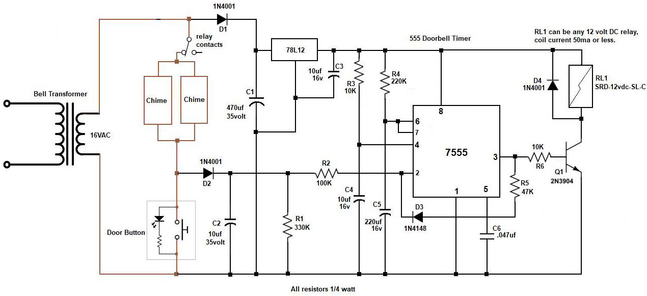
Here's a schematic for a timer circuit using a 7555 chip, cmos version of a 555. This circuit is basically a one shot multivibrator controlled by the doorbell button. With the values shown, the relay will activate (disconnecting power to the chimes) in 6 seconds if the button is held in. After appx 60 seconds the relay will deactivate. If the button is still held in at this time or shorted, the relay will re-activate in 2 seconds and the timing cycles will begin again, 60 seconds off, 2 seconds on. If the button is released during the 60 second deactivation time the circuit will return to the standby state after this time has expired.
The 12 volt regulator is required due to the appx 28 volts the bell transformer will produce. C2 provides the initial 6 second delay period as it discharges through R1 when the button is pressed. C4 and R4 set the 60 second timer. D3 and R5 provide positive feedback to pin #2 and this sets the 2 second timer. When power is first applied C3 and R3 hold the reset pin #4 low for a brief period to make sure the timer will begin in the standby state.
Steve Ghioto
Atlantic Beach, FL
The simplest solution is to use a time-delay fuse of proper rating, with protection applied to each of his two doorbell devices. Suitable 0.25” x 1.25” devices are made by Bussmann type MDL and Littelfuse type 313.
First, it is necessary that the RMS current demand of the doorbell mechanisms be known. This might be a value obtained from the manufacturer, or by measurement using a true-RMS ammeter (or using a true-RMS voltmeter measuring the voltage drop across a small resistance — say, one ohm — and computing the RMS current using Ohms Law).
The Bussmann characteristic curves for MDL time-delay fuses can be found at www.cooperindustries.com/content/dam/public/bussmann/Electrical/Resources/product-datasheets-a/Bus_Ele_DS_2004_MDL_MDL-V.pdf.
Let’s assume that the doorbell device draws one ampere RMS, and that it is desirable that the fuse will operate after five seconds of continuous circuit current. Using the characteristic curves, circuit current (amperes) is displayed on the horizontal scale, and time (seconds) is displayed on the vertical scale. Find the intersection of 1 ampere and 5 seconds on the chart. The next-larger fuse (curved line) is labelled “3/10.” This indicates that a Bussmann type MDL fuse rated for 3/10 amperes will support a 1-ampere load for nearly 7 seconds, which is a close-enough solution to the problem.
Similarly, the characteristics of Littelfuse type 313 time-delay fuses may be found at www.littelfuse.com/~/media/electronics/datasheets/fuses/littelfuse_fuse_313_315_datasheet.pdf.pdf.
Applying the same reasoning, a Littelfuse type 313 fuse rated at 3/8 amperes will clear in just over five seconds while conducting a one-ampere RMS continuous load.
Bussmann and Littelfuse also make fuse holders. For this application a leaded (in-line) plastic fuse holder might be best — Littelfuse #150HV.
Be sure to buy some spare fuses. Good luck.
Peter Goodwin
Rockport, MA
The best approach: Scrap your chimes and buttons and buy a set of wireless chimes and weatherproof buttons. No wires, no transformer, no fuse, no time-out circuit. Amazon lists several types for under $US 30.
Jon Titus
Herriman, UT
It seems to me you don’t need a circuit. If the switch contacts fuse and short the circuit, your problem is current flow. Too much and the contacts arc, fusing the contacts. You need to add some resistance to the circuit with the contacts.
I would start with 50 ohms. Just tie in series with on leg of the switch. If the doorbell still rings go to 75 ohms, 1 watt should be suffice. You can go to 100 ohms if it still rings.
It really doesn’t take a lot of current to ring that doorbell. What we want to do is limit it, to protect the contacts in the switch. If we put a timing circuit in, it will only start ringing again after the time out. With 75 or 100 ohms, your going to cut down that current. Good luck, limit the current.
Thomas Sides
Phoenix, AZ
The simple answer is: a 1.25 amp fuse. But I suspect the more complete answer is that the inductive “kick” from the two chime coils is welding the pushbutton contacts closed.
Weather usually makes switches fail open, not shorted. To prevent the welding you need a surge suppressor across the chime coils. A suitable part is the Cornell-Dubilier Quencharc # 104M06QC-22. Available at Allied, Digikey and a bunch of other places.
If money is critical, just one should do. But if you can afford it, put one across each chime coil.
Chip Veres
Miami, FL
The simplest (though embarrassingly low-tech) method is to put a power resistor (a few ohms, 5 watts) in series with a normally-closed thermal switch (opening about 50 °C) in one leg of the line from the transformer. Epoxy the resistor to the switch, wrap with a bit of fiberglass pipe insulation, and tuck it into a small bottle.
As current flows, the resistor drops a few volts and gets warm, opening the switch. The thermal insulation keeps it from cooling off too quickly, so the power doesn’t cycle on as often. Each time the switch resets, the chimes will remind you to fix the button. Check the current draw of the chimes, and select a resistor that drops two or three volts -- enough power to get warm; not enough to interfere with the chimes.
Use any “junkbox” parts on hand, as values are not critical. BTW, keep the switch assembly inside where it won’t get too cold to shut off.
Bresnik
via Internet
I am a retired Field Service Engineer. Over a decade and a half after early retirement from IBM, a friend asked if an idea he had could be built. I assured him it could.
He offered me partnership if I would design and build a demonstration system. I designed, built, and programmed a system that works just like he wanted it to. An existing patent that I could find no work-around for expires this year. We'd like to have systems ready to go before we start doing demonstrations.
Now, I need to convert my proto-board to a more compact layout to be mass produced. The problem is that all the design software I've found requires that work be done online. Not even a simple schematic design without being on the Web.
I need recommendations for offline software to generate a file for use by a production service. All I'll need is a library of templates for basic TH mounting components. I do not intend to put the results out in the clouds because oftentimes when I look to the clouds, there be vultures about.
#8173
T. A. Rooks
Chelsea, AL
Please log in to post an answer.
Answers
A few years back my company outgrew the CAD software we were using. We spent several weeks looking at all of the available options, and ultimately settled on DipTrace. Ever since then I have been EXTREMELY pleased with it.
You can download a totally free version that is limited to 300 pins, or a 30-day time-limited version that has no pin limit. Diptrace is easy to learn and has all of the features of the “big guys.” By the way, I see you’re in Chelsea, AL. That’s just a few miles from me. Look me up in the phone book if you’d like to talk about this.
Rick Curl
Pinson, AL
Eagle from Autodesk is what most folks use. There is a free version to do a small board. KiCAD is the open-source alternative.
Chip Veres
Miami, FL
I have been using KICAD for six or so years for all the reasons you have listed. It smoothly does the entire process, from schematic capture, parts selection to layout. Layout produces Gerber files which most PCB vendors accept. You can export a parts list to Excel. With a little more work you can produce assembly drawings.
The libraries are adequate for most purposes and component design, although a little non-intuitive, is easy to learn in an hour or two.
All your work stays on your computer. No clouds, no proprietary formats, no lock in with a particular vendor.
Mike Egan
Manchester, NH
Howdy Neighbor! Just a few miles from you here in Shelby! I, too, despise any all cloud-based software. I do not trust the cloud with my data.
I have been using Eagle CAD ever since it was shipped on 3-1/2” floppy disks and I have never had a single problem with it. The software has recently been purchased by Autodesk, but it seems to still be the same offline version as before.
There is a subscription for commercial use, but the free version has always been enough for me. This will run on Windows, Mac, or my personal choice, Linux. Plus, if you run Ubuntu, you can still find the old, pre-Autodesk version still in the repositories.
Other Linux programs include KiCad, Eeschema, and Fritzing, although I think this one may be too basic for your needs. I am sure others can suggest Windows solutions. Good luck!
Derek Tombrello
Shelby, AL
I like to use KiCAD. It is a powerful program that allows you to design circuits, board layouts, and create the files necessary to send to the PCB Fabricator. Of course there is a learning curve but there is also a strong support community.
The manuals are available in .PDF format. You can also create your own components if needed. It installs on your computer and does not require an Internet connection. I hope that this helps.
Richard R, Pope
Reedsburg, WI
I have been using DipTrace for over 10 years and have found it to be very easy to use. There is a free copy available for download where the only limitation is the number of pins. I have also found that www.oshpark.com has very reasonable prices for circuit boards. You can zip the DipTrace build files and upload them directly.
Larry Cicchinelli
Candenton, MO
If you’re willing to pay about $50 or so, I can thoroughly recommend SPRINT LAYOUT 60 from a german compny called ABACOM.
Provided you don’t want more than two layers, (and even that limitation can be got round for an extra layer or possibly two) it allows placment to 1 mil and track widths of your choice, with a good library of components, which you can design yourself if necessary.
Output Gerber files for professional printing, or you can do it yourself to laser or inkjet if you wish, evn allowing percentage corrections to get the print to equal the drawing.
You can download trial software to assess, but it doesn’t allow a print from the trial layout.
Lloyd Stickells
UK
DesignSpark PCB layout and schematic capture. It's well supported and stand alone.
Richard Tomkins
Ottawa, Ontario, Canada
I favor Fritzing, free, open source and aimed at beginners.
Others that are available: Kicad, Geda , both open source as well. Also very popular is Eagle (now owned by Autodesk). The first 3 run on your local machine, I think eagle does as well but haven’t used it.
Peter Van Epp
Vancouver/Canada
I also have investigated this problem. I sometimes use my laptop offline and wanted to work on schematics while waiting in the car when a friend had doctor appointments.
I found that KICAD could be used offline by setting proper directory settings.
- Copy the library files located at C:\Program Files\KiCad\share\kicad\ to your documents folder i.e I use ../documents/kicad/...
- Change the Kicad environment variables to point to the off-line locations KIGITHUB = path to library (schematic symbols) KISYSSYM = path to symbols KISYSMOD = path to footprints KISYS3DMOD = path to 3d shapes KIGITHUB = C:\Users\\Documents\kicad\library KISYSSYM = C:\Users\\Documents\kicad\library KISYSMOD = C:\Users\\Documents\kicad\modules KISYS3DMOD = C:\Users\\Documents\kicad\modules\packages3d
- Open C:\Users\\AppData\Roaming\kicad\fp-lib-table Search and replace all “(type Github)” to “(type KiCad)”
Jan Zumwalt
Arco/ID
There are a number of programs available. One popular one is Eagle PCB. However, I prefer a program called DipTrace for its ease of use and capability. Both Eagle and DipTrace have free trial and low cost limited versions. Good Luck with your product.
Jim McGrew
Saline, MI
I’m trying to bring an old tube transmitter back to life. The power supply uses oil filled capacitors, which don't seem to have handy replacements. Assuming that I can change the oil to reduce the leakage current, what kind of oil is used?
Will motor oil work, for example?
#8172
William Helm
Eugene, OR
Please log in to post an answer.
Answers
I would not try it. Many old oil filled capacitors used oil that contained PCB (polychlorinated Biphenyl). This is classified as Hazardous Waste by the EPA.
I have replaced electrolytic capacitors in several old radios in the past few years. The problem with compatibility is that new capacitors are a lot smaller than the old ones were. That's a nice problem to have but mounting them can be a bit difficult if you are wanting to use the same holes. Find modern dry replacements at places such as Digi-Key or Mouser Electronics with the same capacity in pico Farads or micro Farads and the same or higher voltage rating and you should be OK.
Don Pitchford
Springfield, IL
I don’t know why you are concerned with leakage in a filter capacitor. If the capacitor is doing its job of smoothing out the DC and is not overheating, it should be fine. If the cap is buzzing or sizziling, throw it away. Good luck on your project, and be careful; voltages in a transmitter can be quite high.
Russ Kincaid
Milford, NH
OK, I'll bite. No, you can't take your caps to a garage for an oil change. 😊
There are a number of vendors (for instance Antique Electronic Supply) who sell modern replacement parts. Most capacitors (other than Mica and Ceramics) are subject to suspicion, and if you have no way to test them, replacement would be prudent. Resistors can also drift in value, especially those that get hot. Restoring tube equipment is a lot of work, but very satisfying.
Bill van Dijk
Ottawa, Canada
SAFETY WARNING: If the cap doesn't clearly say "NO PCBs" LEAVE IT ALONE. It may contain oil contaminated with dioxin, a potent poison. With that said, what kind of transmitter are you working on anyway?? I have never heard of changeable oil in a cap smaller than used by an electric utility.
If you really want to make the change, you want non-PCB transformer oil. The second-best alternative is Johnson's Baby Oil.
Chip Veres
Miami, FL
Changing the oil is hazardous (most oil capacitors used toxic polychlorinated biphenyls) and useless, as leakage is most likely due to damage to the paper separator immersed in the oil. Better just look for an equivalent value capacitor.
If it's a high-voltage power supply cap, you can use modern electrolytic capacitors. If you need to put two or more (identical!) capacitors in series for higher voltage rating, put large equalizing resistors across each (e.g. 500 kilohm or 1 megohm ) and remember that capacitance decreases according to the number in series (e.g. two 20 microfarad caps in series are 10 microfarads).
Bresnik
via Internet
I’ve never heard of refilling that size capacitor, but I do have some experience with much larger ones.
We had a number of very large capacitors that our lab received from a national laboratory as part of a research project. They originally had transformer oil as a dielectric but the outer cases were cracked and it had leaked out. Because of the problems at that time with transformer oil containing high levels of PCBs, we used castor oil as a substitute with good results. I have no idea if motor oil would work but I wouldn’t recommend it.
Jeffrey Tuttle
Mahopac
Please do not attempt this. Many oil filled capacitors used oil that contained PCBs — a carcinogen. They should be disposed of as VERY hazardous waste. PCBs were banned sometime in the 70s.
A product that I worked with contained oil filled capacitors and we had to change over to new types. It is almost certainly NOT motor oil. There seem to be a fair number of antique radio restoration enthusiasts, so you might try a web search. Also, just search for the model and manufacturer of your transmitter. Any markings on the capacitor will also be useful.
You might also look up references to the American Radio Relay League (ARRL). They have been the technical center for amateur radio for a very long time. If your transmitter is home made (home brew), it might be one that they described in one of their handbooks or a QST maazine. You can probably find a few ARRL Amateur Radio handbooks (annual publications) at your local library.
HJ
MN
Please do not open or handle oil filled capacitors. The oil in most oil filled caps is poisonous. PCB’s are a known carcinogen. Not all capacitors containing PCB’s are marked. Many of the older capacitors from high voltage power supplies are suspect. Our standard operating procedure with oil filled caps that were leaking or bulging was to put in a metal can, then fill the container with cat litter and then handle as if it was Hazmat.
Steven K Ashcraft
Mineral Wells, WV
I want to convert a 3D printer to a laser burning station to work with wood veneers and leather goods.
Any advice on the best type and color of laser to get? I’ve heard brown wood and leather reflect more red light and so I should use a blue laser.
#8171
Kyle Hoyos
Walkerton, IN
Please log in to post an answer.
Answers
What you need to burn and/or cut leather is a CO2 laser. These lasers will cut almost anything that is not metal. For metal you need a YAG laser. There are many, many small used machines on eBay. Look for brands by the names of Epilog, Universal, Trotec. 25 watts is a nice start for burning/engraving and very slow cutting. When we cut we like to use our 400 watt laser.
I might note that engraving/cutting leather makes a real bad smell!
Rick Cordary
Fort Lauderdale, FL
My wife and I are hearing impaired. We need an AVC amplifier for TV audio to keep the level constant going into WiFi to hearing aids. Commercial or build-it-yourself (no surface mount); Analog not digital.
#9173
Fred Imm
Kirtland, OH
Please log in to post an answer.
Answers
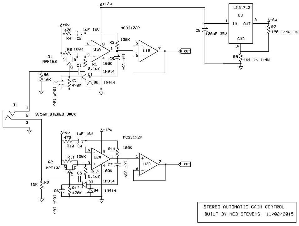
Here's a schematic from my archives that provides dual compression (signal and gain) using cadmium photo cells as variable resistors. Not normally seen in audio circuits photo cells actually have a fast enough response. This amp is designed for line level input and can use the USB jack on the TV for power (+5 volts).
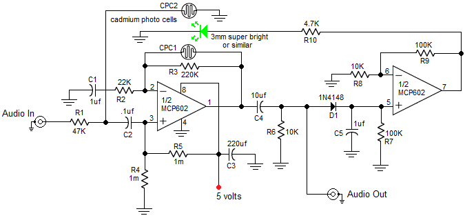
The first half of U1 is the audio amp, second half is a DC amplifier to drive the LED. Limiter operation goes into effect when the LED begins to illuminate as the audio level increases. This causes both photo cells to decrease in resistance lowering the gain of the amp as well as the signal level at the input. The LED will need to be physically mounted between the photo cells in a light tight enclosure as seen in the schematic for best operation.
Steve Ghioto
Atlantic Beach, FL
Devices I use that probably would do the job may not be directly applicable, but should give you some ideas.
Devices are called audio compressors or pedal amplifiers. They reduce the dynamic range of signals by amplifying the low signal levels and compressing the high signal levels.
I use a Sampson MXP124 microphone mixer. It has two channels with audio compression available. Simple, single knob per channel. Works well for what I use it for, which is a longer story not relevant here. Sampson may make much simpler equipment with similar audio compressors.
I also use a Dunlop MXR M-132 pedal amp or super compressor. Intended for professional guitar use, it is a single channel, and includes variable attack and gain. I use it with a 9-volt battery but the manual says an AC adapter is available.
Excellent device, small, but single channel (no stereo). (Pedal amplifier is a music term, do not worry, no feet required.) Again — these are sources of ideas, not necessarily solutions.
Orv Barr
Livermore, CA
Right now, there are 304 "audio compressors" listed on ebay. Pick one within your price range and go for it.
Chip Veres
Miami, FL
What you want is to dynamically increase the volume of the soft passages, and diminish the volume of the loudest passages. The circuit to do this is called a compressor/limiter.
You don’t want a simple passive circuit because when you are hearing impaired, you need to retain the clarities and minimize the distortion of the higher frequencies to distinguish consonants and articulation of speech, and you don’t want to muddy the lower frequencies so you can catch inflection and vowels.
Radio stations (and to some extent TV stations) employ this to maximize modulation (so their signal comes in stronger) and yet not so loud as to over-modulate per their license.
As you experience in TV, marketing companies use separate circuits for each narrow band of frequencies to blast out commercials as loud as possible over the program material. But now you’ve got program material with softer speech passages and louder music passages and loud commercials. This is where the compressor/limiter comes in for hearing impaired use.
There are numerous examples available of all varying complexities, such as this one from Georgia Tech University: http://leachlegacy.ece.gatech.edu/ece4435/sp08/sp08dp06.pdf, or this one based on an Automatic Gain Control circuit by Jim Keith on Electro-Schematics: www.electroschematics.com/9400/audio-compressor-agc.
I myself am using a a circuit based on the TDA1054 IC as described here by P. Marion: www.electroschematics.com/232/audio-compressor.
Scott Hall
Raleigh, NC
I have a water softener that needs pellet salt added to a brine tank. I’m trying to figure out a circuit to detect when I need to add salt as the tank is opaque and salt usage varies depending on use. The simpler the circuit, the better!
#7174
Salt Sensor
Greensboro, NC
Please log in to post an answer.
Answers
You’re in my neck of the woods, and I’ve just solved the very same problem. I just used a simple LED source and phototransistor target to shine a beam across the salt tank at the height where I need to refill the salt.
The transistor’s output is fed into an ESP8266 microcontroller board (the “Espee”) that has built-in WIFI and can be programmed via the Arduino IDE (refer to some Nuts & Volts articles on the ESP8266).
This way, you display an alarm on a webpage generated on the Espee, or even have it send a SMS message to your phone or messaging application. The low-cost (~ $7) ESP8266 (and its more powerful cousin, the ESP2 with bluetooth) has become the basis of many IoT (Internet of Things) circuits and smart-home setups.
If you are having trouble finding the Nuts & Volts articles on programming this wonderful device, here is one on loading the Arduino IDE for the ESP8266: www.whatimade.today/esp8266-easiest-way-to-program-so-far
Scott Hall
Raleigh, NC
No circuit needed. Just put a recurring “meeting” on your Google or other calendar to pop up a message on the first of each month that notes: “Check Salt.” Or check it more often if you choose. I check on the first and 15th of each month.
Jon Titus
Herriman, UT
With high powered laser prices dropping like crazy, I decided to pick up a 3W blue laser from eBay for $50 to experiment with.
I’m concerned about eye damage and would like some advice on eye protection. What makes a pair of laser goggles good and what should I stay away from?
#7173
Gary Byrum
Milwaukee, WI
Please log in to post an answer.
I have an older model Hunter SRC sprinkler controller that came with my house. Recently, the unit has been “resetting” to 12:00 am rather than keeping time. The unit has a nine volt battery that was reading 2.7V, so I replaced the battery. Within a week, the problem was back and the new battery was also dead (3.1V).
Any ideas what could be killing the batteries? I can’t find a schematic for this unit.
#7172
Norris Shaw
Santa Ana, CA
Please log in to post an answer.
Answers
No doubt an electrolytic cap in the power supply has excessive leakage. You could replace all electrolytics but the large one in the power supply is most likely the culprit.
Russell Kincaid
Milford, NH