September 2017
I need a way to protect my hardwired door chimes from being accidentally “burnt up” when the doorbell button gets stuck.
A couple of times when the button got stuck, I was home and able to fix it before damage occurred. The last time it happened, however, nobody was home. Someone came to the door, and we arrived home to the smell of burnt electronics.
I’ve replaced the button more times then I can count. I guess the way the weather hits it — eventually — it becomes stuck. I am now on my third set of replacement chimes.
I have TWO 16 volt chimes (10VA) wired to a single button (LED lamp) on a 16V 30VA transformer. The transformer is much larger than normal to accommodate the two chimes.
I would like to protect the chimes in one of two ways:
1) Simple protection — Inline fuse that would blow if the chimes were pulling current for more than (let's say) five seconds. I figure a “slow-blow” fuse would be ideal, but not sure on the rating.
2) More complex protection — A “time out” circuit that would cut power to the chimes if the circuit was live for more than five seconds, self-resetting either after the button was released or after 60 seconds (chime would activate again, indicating a stuck button).
Please log in to post an answer.
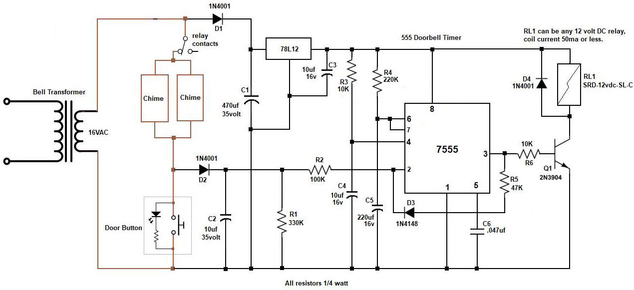
Here's a schematic for a timer circuit using a 7555 chip, cmos version of a 555. This circuit is basically a one shot multivibrator controlled by the doorbell button. With the values shown, the relay will activate (disconnecting power to the chimes) in 6 seconds if the button is held in. After appx 60 seconds the relay will deactivate. If the button is still held in at this time or shorted, the relay will re-activate in 2 seconds and the timing cycles will begin again, 60 seconds off, 2 seconds on. If the button is released during the 60 second deactivation time the circuit will return to the standby state after this time has expired.
The 12 volt regulator is required due to the appx 28 volts the bell transformer will produce. C2 provides the initial 6 second delay period as it discharges through R1 when the button is pressed. C4 and R4 set the 60 second timer. D3 and R5 provide positive feedback to pin #2 and this sets the 2 second timer. When power is first applied C3 and R3 hold the reset pin #4 low for a brief period to make sure the timer will begin in the standby state.
The simplest solution is to use a time-delay fuse of proper rating, with protection applied to each of his two doorbell devices. Suitable 0.25” x 1.25” devices are made by Bussmann type MDL and Littelfuse type 313.
First, it is necessary that the RMS current demand of the doorbell mechanisms be known. This might be a value obtained from the manufacturer, or by measurement using a true-RMS ammeter (or using a true-RMS voltmeter measuring the voltage drop across a small resistance — say, one ohm — and computing the RMS current using Ohms Law).
The Bussmann characteristic curves for MDL time-delay fuses can be found at www.cooperindustries.com/content/dam/public/bussmann/Electrical/Resources/product-datasheets-a/Bus_Ele_DS_2004_MDL_MDL-V.pdf.
Let’s assume that the doorbell device draws one ampere RMS, and that it is desirable that the fuse will operate after five seconds of continuous circuit current. Using the characteristic curves, circuit current (amperes) is displayed on the horizontal scale, and time (seconds) is displayed on the vertical scale. Find the intersection of 1 ampere and 5 seconds on the chart. The next-larger fuse (curved line) is labelled “3/10.” This indicates that a Bussmann type MDL fuse rated for 3/10 amperes will support a 1-ampere load for nearly 7 seconds, which is a close-enough solution to the problem.
Similarly, the characteristics of Littelfuse type 313 time-delay fuses may be found at www.littelfuse.com/~/media/electronics/datasheets/fuses/littelfuse_fuse_313_315_datasheet.pdf.pdf.
Applying the same reasoning, a Littelfuse type 313 fuse rated at 3/8 amperes will clear in just over five seconds while conducting a one-ampere RMS continuous load.
Bussmann and Littelfuse also make fuse holders. For this application a leaded (in-line) plastic fuse holder might be best — Littelfuse #150HV.
Be sure to buy some spare fuses. Good luck.
The best approach: Scrap your chimes and buttons and buy a set of wireless chimes and weatherproof buttons. No wires, no transformer, no fuse, no time-out circuit. Amazon lists several types for under $US 30.
It seems to me you don’t need a circuit. If the switch contacts fuse and short the circuit, your problem is current flow. Too much and the contacts arc, fusing the contacts. You need to add some resistance to the circuit with the contacts.
I would start with 50 ohms. Just tie in series with on leg of the switch. If the doorbell still rings go to 75 ohms, 1 watt should be suffice. You can go to 100 ohms if it still rings.
It really doesn’t take a lot of current to ring that doorbell. What we want to do is limit it, to protect the contacts in the switch. If we put a timing circuit in, it will only start ringing again after the time out. With 75 or 100 ohms, your going to cut down that current. Good luck, limit the current.
The simple answer is: a 1.25 amp fuse. But I suspect the more complete answer is that the inductive “kick” from the two chime coils is welding the pushbutton contacts closed.
Weather usually makes switches fail open, not shorted. To prevent the welding you need a surge suppressor across the chime coils. A suitable part is the Cornell-Dubilier Quencharc # 104M06QC-22. Available at Allied, Digikey and a bunch of other places.
If money is critical, just one should do. But if you can afford it, put one across each chime coil.
The simplest (though embarrassingly low-tech) method is to put a power resistor (a few ohms, 5 watts) in series with a normally-closed thermal switch (opening about 50 °C) in one leg of the line from the transformer. Epoxy the resistor to the switch, wrap with a bit of fiberglass pipe insulation, and tuck it into a small bottle.
As current flows, the resistor drops a few volts and gets warm, opening the switch. The thermal insulation keeps it from cooling off too quickly, so the power doesn’t cycle on as often. Each time the switch resets, the chimes will remind you to fix the button. Check the current draw of the chimes, and select a resistor that drops two or three volts -- enough power to get warm; not enough to interfere with the chimes.
Use any “junkbox” parts on hand, as values are not critical. BTW, keep the switch assembly inside where it won’t get too cold to shut off.