The two circuits Nate submitted are configured to turn the LED sequencers ON during the day and OFF at night. This is because the resistance of the photocell decreases as light falling on the photocell increases, causing increased current flow from the base of the transistor to the positive power supply rail. The increase in base current will cause the transistor to conduct and supply current to the LED sequencer circuits in daylight. To modify the circuits so they turn OFF during the day and ON at night, swap the photocell and the resistor so that decreasing photocell resistance will pull the base of the transistor toward ground, turning the transistor off in the daytime. The fixed resistor will turn the transistor on at night when the resistance of the photocell is high compared to the resistor. The circuit can be improved (see new diagram in Figure 1). Two issues are solved by the improved circuit.

1) Nate is using a 2N2222 transistor as a low side switch to control current to the light sequencer circuits. A MOSFET makes a better switch because it has a very high OFF resistance and a very low ON resistance, so more of the supply voltage is applied to the light sequencer circuit and less power is wasted in the transistor. For this reason, I replaced the 2N2222 transistor with a low cost IRF510 N-channel power MOSFET.
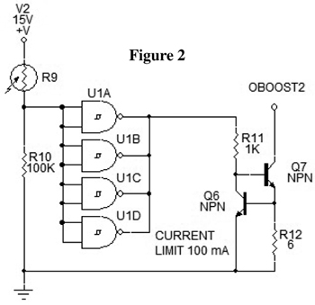
2) The other problem with Nate's circuits is they won't turn on and off quickly like a mechanical switch. At dawn and dusk — when the light changes gradually — the current through the transistor will also change gradually. The switching action should happen fast when a predetermined light threshold is crossed; a Schmitt trigger circuit is needed for that. The improved circuit contains four Schmitt trigger NAND gates in a single 4093 CMOS IC. Only one NAND gate is needed, so the other inputs should be tied to V- to prevent instability.
The 4093 has a hysteresis band which keeps the sequencer circuit from receiving rapid bursts of current at dawn and dusk when the control voltage hovers near the tripping point. The output of the 4093 drives the IRF510 MOSFET which switches the current to the LED light sequencer circuit on and off. The MOSFET is driven into saturation by the 4093 Schmitt trigger to provide clean switching and maximum current to the LED sequencer circuit. Next, the answers to questions a, b, and c.
a) Will any photoresistor work?
Most photocells will work with the improved circuit, but don't confuse a photocell (which is a photoresistor) with a phototransistor. I've included a pot wired as a variable resistor; this will adjust the voltage divider to match the photocell characteristics. To set the pot, go outside in the twilight near sunset and adjust the pot until the circuit turns ON, then back off slowly until it turns off. The LED sequencer circuit should then turn on at sunset and off at sunrise.
b) What are the optimum photoresistor light/dark resistance values?
The resistance of most photocells varies from a few hundred ohms (or less) in direct sunlight to a megohm (or more) in total darkness. The optimum resistance of R1 for a given photocell can be calculated using Ohm's Law, but the adjustment pot in the improved circuit makes it compatible with most CdS photocells.
c) What formula will calculate the optimum component values?
The 2N2222 transistor used in Nate's circuits is a current operated device which should be explained in terms of current. The improved circuit uses voltage controlled components. This explanation is only for the improved circuit.
Inputs 1 and 2 of the 4049 are tied together and connected to a voltage divider consisting of photocell PC1 and resistor R1, which are connected in series between V+ and V-. To predict circuit operation in different lighting conditions, calculate the voltage from V- to the point where R1 and PC1 join using Ohm's Law, and then compare this voltage to the upper and lower trip points of the 4093. The lower trip point will turn the LED sequencer circuit on because the 4093 is an inverter, which will drive the gate of the MOSFET to V+ when the 4093 input is low. When the MOSFET conducts, it will ground the LED sequencer circuit to V-. The lower trip point of the 4093 is +3.9 volts when V+ is 10 volts and the upper trip point is +5.9 volts.
EVENING CONTROL: The voltage across R1 must fall below 3.9 volts to turn the LED sequencer on at sunset; this example uses 3.5 volts to be well below the threshold. To calculate the optimum resistance of R1, it's necessary to know the resistance of PC1 in the twilight hours of sunset or dawn.
This example assumes the resistance of PC1 is 100K at sunset. The voltage drop across both resistors must add up to V+. So, if V+ is 10 volts, then 6.5 volts must be dropped across 100K (PC1) for 3.5 volts to be dropped across R1. Operation of the improved circuit is explained in four steps.
STEP 1: Calculate the current through the voltage divider at sunset.
If we know the resistance of PC1 and the voltage across it, then we can calculate the current through PC1 with Ohm's Law (I = E/R). Plugging in the known values, I = 6.5/100,000 = 65 µA. This is a series circuit, so 65 µA also passes through R1.
STEP 2: Calculate the resistance of R1.
We know the current through R1 is 65 µA and the voltage across R1 is 3.5 volts, so we can use another form of Ohm's Law (R = E/I) to calculate the resistance of R1. R1 = 3.5/.000065 = 53846 ohms. To check this, use E = IR, E = .000065 (53846) = 3.499 volts; 3.5 volts is under the lower trip point of the 4093, so output pin 3 of the NAND gate will go high, driving the gate of the IRF510 MOSFET to V+ through R2. This causes the MOSFET to conduct and provide a current path from V- to the LED sequencer circuit.
MORNING CONTROL: At the soft light near daybreak, a typical photocell has a resistance around 10K. If we use the value of 53.846K previously calculated for R1 and assume a PCI resistance of 10K at dawn, then the total resistance of PC1 + R1 is 10K + 53.846K = 63.846K.
STEP 3: Find the daytime current through the voltage divider.
If V+ is 10 volts, the current through the series resistances PC1 and R1 at sunrise can be calculated with I = E/R. I = 10/63846 = .0001566 A, or 157 µA.
STEP 4: Find the daytime voltage drop across R1.
Now that we know the morning current through R1 and the resistance of R1, we can calculate the morning voltage drop across R1 with E = I/R; E = .0001566 (53846) = 8.43. A daytime voltage drop across R1 of 8.43 volts is well above the 5.9 volt upper trip point of the 4093, so the output of the inverting 4093 will go low, grounding the gate of the MOSFET to V- and turning off current to the LED sequencer circuit. During the day, the input to the 4093 should vary between 8 and 10 volts, keeping the LED sequencer circuit turned off.