With TJ Byers
Simple Capacitance Meter
Question:
I have a need for a simple capacitance meter. It doesn't have to have a digital readout or a microcontroller. A 555 timer chip with a whistle is more than adequate. A comparative tester is all I really need.
Bob Fredericks
via Internet
Answer:
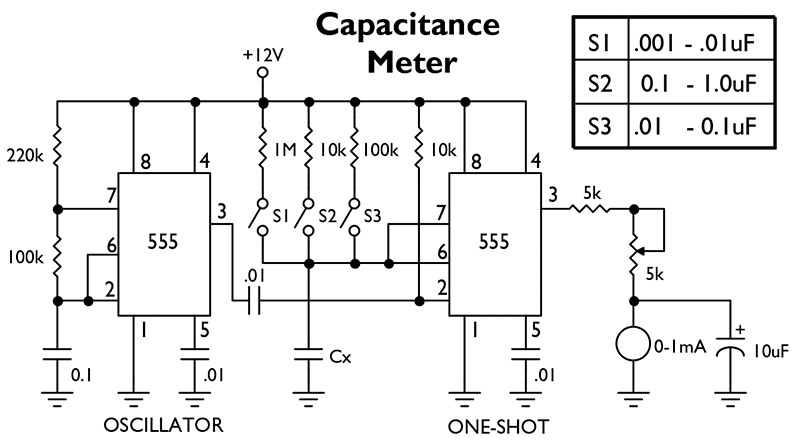
A capacitance meter using a 555 timer? This is a relatively simple design (originated by TI, I believe) with amazing accuracy. Basically, it consists of a monostable (one-shot) RC multivibrator clocked by an astable RC oscillator — both based on the 555 timer.

When the oscillator triggers the one-shot, it begins charging the unknown capacitor, Cx. The rate of charge is equal to t = RC, and the trigger point is t = 1.1RC. Because this is nearly a linear function, it's very easy to translate the value of the capacitor into a pulse width, which now becomes a PWM (pulse-width modulated) signal with the timing of the astable clock. From here, the output pulse is averaged by an analog voltmeter. If R is 100K and C is 0.1 µF, then the output voltage is 10 volts. Switches S1 through S3 expand the range to include capacitors with values ranging from 100 pF to 1 µF. Increasing and decreasing the value of R in increments of 10 can extend that range down to 10 pF and up to 100 µF. Be aware that at the bottom end (lower capacitance), the accuracy falls off due to stray capacitance and other lossy factors. To calibrate the meter, insert a 0.1 µF capacitor across Cx, select S2, and adjust the 5K pot until the 0-1 mA meter reads full scale. The accuracy of the meter between the ranges depends on the accuracy of the timing resistor, R. If you use 5 percent resistors, then expect up to a 5 percent error as you switch ranges. The 12-volt line must be held constant using a voltage regulator, such as an LM78L12.


Comments