With TJ Byers
Digital Potentiometer Manual Control
Question:
I plan to make a stereo amplifier using an LM4753 that uses a DC volume control. Instead of using a volume control, I would like to know if I could use a digital potentiometer. Catalyst makes them and Mouser sells them for less than $2.00. Can you supply a diagram of how to use a digital pot for audio purposes?
Robert Jemmings
Rehoboth Beach, DE
Answer:
First, some reader background: A digital potentiometer is basically a DAC device that mimics the operation of a mechanical pot. It does this by using logic switches to tap into an internal ladder resistor. The taps are switched in and out sequentially so that the resistance follows a linear path. The number of taps determines the resistance difference between the steps and the resolution (coarseness) of the pot. The higher the number of taps, the smoother the operation.
For example, a 10k pot with 32 steps has a resistance change of 312.5 Ω per step, whereas a 10k pot with 256 steps has a resistance change of just 39 Ω per step.
Inside the digital pot is an up/down controller that steers the direction of the taps. The user interfaces this controller through three methods.
One method uses computer protocols — like I2C or SPI — to name but a few. Other digital pots — like the AD5228 from Analog Devices — have internal circuitry so that you have only two pins to contend with: increasing resistance or decreasing resistance.
The most popular interface for hobbyist and many audio applications is the incremental up/down method. This uses three inputs. The up/down pin directs the direction of the count and the increment pin provides the clock that steps the controller. The third pin is a chip enable that’s grounded for normal operation.

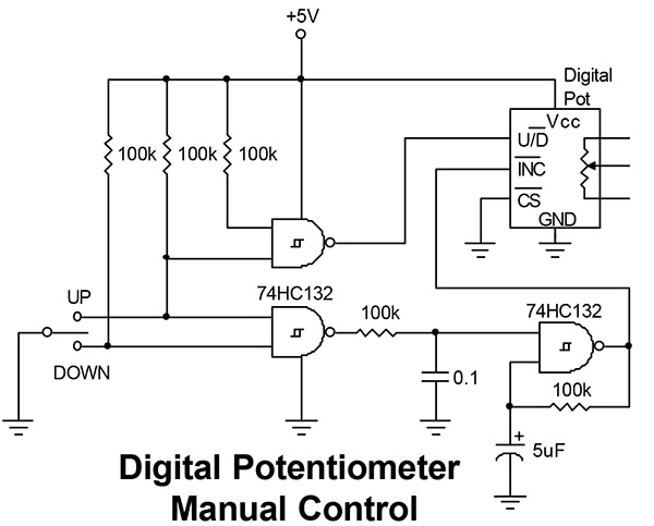
A simple manual interface using this method is shown in above. A momentary SPDT switch with a center off position (RadioShack 275-705) operates the digital pot. When the switch is turned on in either position, it grounds one of the inputs of the lower NAND gate, which forces its “output high. This starts the oscillator (right NAND gate) that clocks the INC input. If the switch is in the UP position, it also grounds the input of the direction gate (upper left), which forces its output high and sets the U/D pin to count up.
The frequency of the square wave oscillator is about 3 Hz; you may want to raise or lower this frequency by changing the 5 mF capacitor to match the step number of your particular pot. A 32-step pot needs
a larger cap (lower frequency) than a 1,024-step pot does.


Comments