With TJ Byers
About Scope Probes
Question:
Recently, I was given two 25-year-old Leader LBO-15A oscilloscopes — dual-channel, 15 MHz. They both work. Having never owned a scope, it would be nice to use them. However, neither came with a probe and I don’t know much about selecting one.
Frank Lemon
Answer:
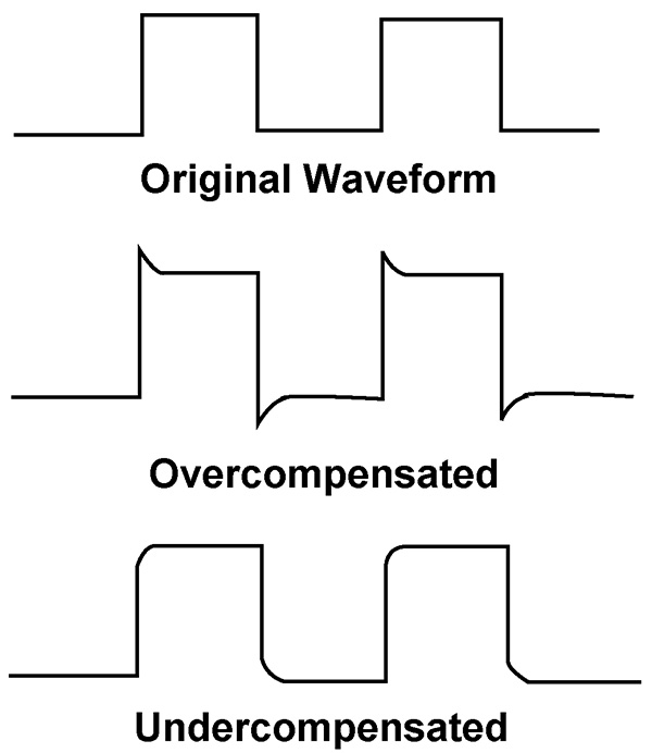
If I were you, I’d buy the 15085 TE scope probe from Marlin P. Jones & Assoc. (800-652-6733; www.mpja.com). It has a bandwidth of 20 MHz and sells for a low $7.95. (MPJA also sells scope probes going up to 200 MHz.) But that’s just the beginning. Unless you properly compensate the probe, you will be displaying the response of the probe itself and not your circuit. Refer to Figures 1 and 2 for this discussion.

Figure 1.
The typical input impedance of an oscilloscope — especially one of that era — is 1 megohm with 50 pF to 100 pF. If you put this load across a high-frequency oscillator, not only will you shift the operating frequency with the added parallel capacitance, but you risk stalling oscillation altogether. Which is why selecting a good scope probe is essential to accurate measurements.
Most probes have an attenuation factor of 10x. A 10x probe has the effect of reducing capacitance by a factor of 10. The trade-off is that it also attenuates the signal by a factor of 10. This means that 10 volts at the source becomes one volt at the scope input.
A 10x probe is made up of a 9 megohm resistor, a 15 pF trimmer capacitor, and a short length of coaxial cable (Figure 1). When added to the 1 megohm resistance of the scope, the probe tip reflects a 10 megohm load to ground. The capacitance, on the other hand, is subtractive, resulting in a reflected load capacitance of 9 pF (with the trimmer set to 11 pF).

Figure 2.
The trimmer is used to compensate for overshoot and undershoot that is common when probing a circuit. This is done in five steps:
- Connect the probe tip to the scope calibrator. (Most scopes provide a 1 kHz square wave calibrator output.)
- Switch the channel input coupling to DC.
- Set the volts/div switch to 1V/div (assuming the calibration voltage is five volts p-p.).
- Set the sweep rate to 1 ms/div.
- Adjust the trimmer until the tops and bottoms of the square wave are flat (Figure 2).


Comments