Our last edition of the Transistor Cookbook series described practical ways of using bipolar transistors in simple, but useful common-emitter and common-base configurations. This time, we'll show various ways of using bipolars in practical small-signal audio amplifier applications.
AUDIO AMPLIFIER BASICS
Transistor amplifiers have many useful applications in mono and stereo audio systems. For most practical purposes, each channel of a stereo system can be broken down into three distinct circuit sections, or blocks, as shown in Figure 1. The first section is the selector/pre-amplifier block. It lets the user select the desired type of input signal source and applies an appropriate amount of amplification and frequency correction to the signal so that the resulting output signal is suitable for use by the second circuit block.

FIGURE 1.
The second section is the tone-/volume-control block, which lets the user adjust the system’s frequency characteristics and output signal amplitude to suit personal tastes. This section may contain additional filter circuits and gadgets, such as scratch and rumble filters, and audio mixer circuitry, etc. Its output is fed to the system’s final section — the audio power amplifier — which drives the loudspeakers. A variety of practical pre-amplifier, tone-control, and associated circuits are described here. Audio power amplifier circuits will be dealt with in a future episode of the series.
SIMPLE PRE-AMPS
The basic function of an audio pre-amplifier is that of modifying the input signal characteristics so that they give the level frequency response and nominal 100mV mean output amplitude needed to drive the amplifier’s tone-control system. If the input comes from a radio tuner, CD player, etc., the signal characteristics are usually such that they can be fed directly to the tone-control sections, by-passing the pre-amplifier circuit. If they are derived from a microphone or an old-style record (disk) pick-up, they usually need modification via a pre-amp stage.
Microphones and pick-ups are usually either magnetic or ceramic/crystal devices. Magnetic types usually have a low output impedance and a low signal sensitivity or mean output amplitude (about 2mV nominal). Their outputs thus need to be fed to high-gain pre-amplifier stages. Ceramic/crystal types usually have a high output impedance and a high sensitivity (about 100mV nominal). Their outputs thus need to be fed to a high-impedance pre-amp stage with near-unity voltage gain.
Most microphones have a flat frequency response and can be used with simple pre-amp stages. Figure 2 shows a unity-gain pre-amp that can be used with most high-impedance ceramic/crystal microphones. It is an emitter follower circuit with a bootstrapped (via C2-R3) input network, and has an input impedance of about two megohms — its supply is decoupled via C4-R5.
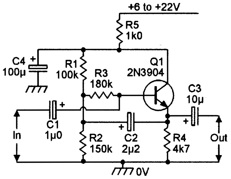
FIGURE 2.
Figures 3 and 4 show pre-amp circuits that can be used with magnetic microphones. The single-stage circuit in Figure 3 gives 46dB (x200) of voltage gain, and can be used with most magnetic microphones.
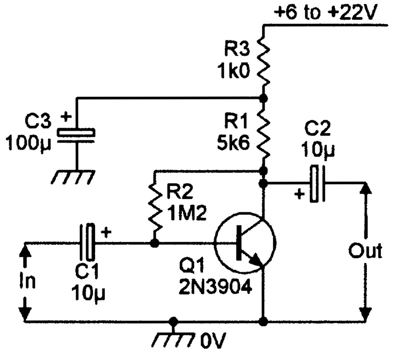
FIGURE 3.
The two-stage circuit in Figure 4 gives 76dB of voltage gain, and is meant for use with magnetic microphones with very low sensitivity.
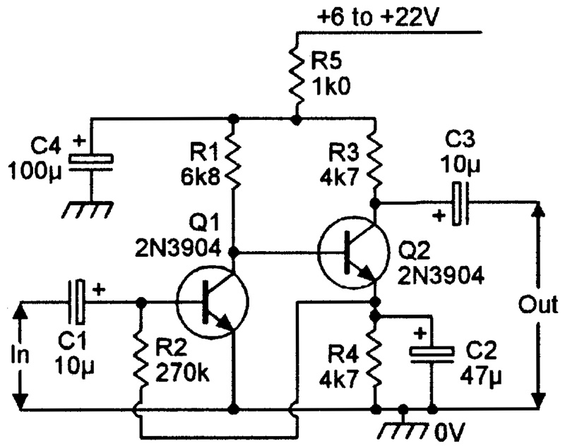
FIGURE 4.
RIAA PRE-AMP CIRCUITS
If a constant-amplitude 20 Hz to 20 KHz variable-frequency signal is recorded on a standard 33.3 RPM phonograph disk (record) using conventional stereo recording equipment, and the record is then replayed, it generates the highly non-linear frequency response curve, shown in Figure 5 — the dotted line shows the idealized shape of this curve, and the solid line shows its practical form. The idealized response is flat between 500 Hz and 2120 Hz, but rises at a rate of 6dB/octave (20dB/decade) above 2120 Hz, and falls at a 6dB/octave rate between 500Hz and 50 Hz. The response is flat to frequencies below 50 Hz.
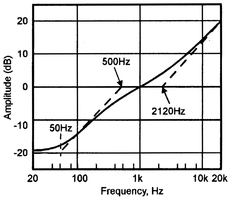
FIGURE 5.
These responses enable disk recordings to be made with good signal-to-noise ratios and wide dynamic ranges, and are used on all normal records. Consequently, when a disk is replayed, its output must be passed to the power amplifier via a pre-amp with an equalization curve that is the exact inverse of that used to make the original disk recording, so that a linear overall record-to-replay response is obtained. Figure 6 shows the shape of the necessary RIAA.
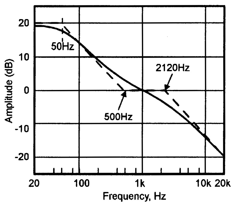
FIGURE 6.
(Record Industry Association of America) equalization curve. A practical RIAA equalization circuit can be made by wiring a pair of C-R feedback networks into a standard pre-amp (so that the gain falls as the frequency rises), with one network controlling the 50 Hz to 500 Hz response, and the other the 2120 Hz to 20 KHz response. Figure 7 shows such an amplifier.
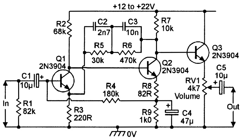
FIGURE 7.
The Figure 7 circuit can be used with any magnetic pick-up cartridge. It gives a 1V output from a 6mV input at 1 KHz, and provides equalization that is within 1dB of the RIAA standard between 40 Hz and 12 KHz. The actual pre-amp is designed around Q1 and Q2, with C2-R5 and C3-R6 forming the feedback equalization network. Q3 is an emitter follower buffer stage, and drives optional volume control RV1.
Ceramic/crystal pick-ups usually give a poorer reproduction quality than magnetic types, but give output signals of far greater amplitude. They can thus be used with a very simple type of equalization pre-amp, and are consequently found in many popular record player systems. Figures 8 and 9 show alternative phonograph pre-amplifier circuits that can be used with ceramic or crystal pick-up cartridges. In each case, the pre-amp/equalizer circuit is designed around Q1, and Q2 is an emitter follower output stage that drives optional volume control RV1. The Figure 8 circuit can be used with any pick-up cartridge that has a capacitance in the 1000pF to 10,000pF range. Two-stage equalization is provided via C1-R2 and C2-R3, and is typically within 1.6dB of the RIAA standard between 40 Hz and 12 KHz.
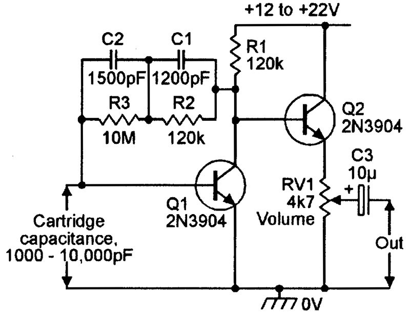
FIGURE 8.
The alternative Figure 9 circuit can only be used with pick-ups with capacitance values in the range 5000pF to 10,000pF, since this capacitance forms part of the frequency response network The other part is formed by C1-R3. At 50-60 Hz, this circuit has a high input impedance (about 600K), and causes only slight cartridge loading. As the frequency is increased, however, the input impedance decreases sharply, thus increasing the cartridge loading and effectively reducing the circuit gain. The equalization curve approximates the RIAA standard, and the performance is adequate for many practical applications.
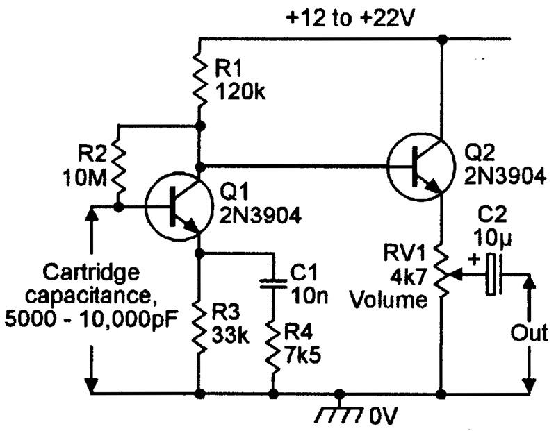
FIGURE 9.
A UNIVERSAL PRE-AMP
Most audio amplifiers use pre-amps with variable characteristics, such as a high-gain linear response for use with magnetic microphones, low-gain linear response for use with a radio tuner, and high-gain RIAA equalization for use with a magnetic pick-up cartridge, etc. To meet this requirement, it is normal to fit the system with a single universal pre-amp circuit of the type shown in Figure 10. This is basically a high-gain linear amplifier that can have its characteristics altered by switching alternative types of resistor/filter networks into its feedback loops.
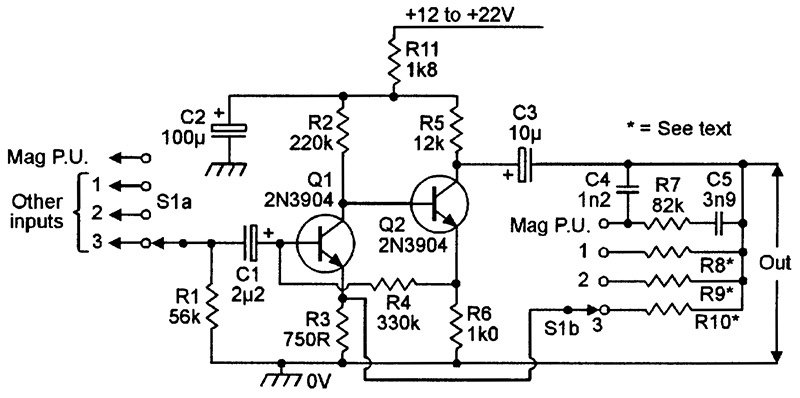
FIGURE 10.
Thus, when the selector switch is set to the “MAG P.U.” position, S1a connects the input to the magnetic pick-up cartridge, and S1b connects the C4-R7-C5 RIAA equalization network into the feedback loop. In the remaining switch positions, alternative input sources are selected via S1a, and appropriate linear-response gain-controlling feedback resistors (R8, R9 and R10) are selected via S1b. The values of these feedback resistors should be selected (between 10K and 10M) to suit individual requirements — the circuit gain is proportional to the feedback resistor value.
VOLUME CONTROL
The volume control circuitry of an audio amplifier system is normally placed between the output of the pre-amp and the input of the tone-control circuitry, and consists of a variable potential divider or pot. This pot can form part of an active circuit, as shown in Figures 7 through 9, but a snag here is that rapid variations of the control can briefly apply DC potentials to the next circuit, possibly upsetting its bias and generating severe signal distortion.
Figure 11 shows the ideal form and location of the volume control. It is fully DC-isolated from the pre-amp’s output via C1, and from the input of the tone-control circuitry via C2. Variation of the RV1 slider thus has no effect on the DC bias levels of either circuit. RV1 should be a log-type of pot.
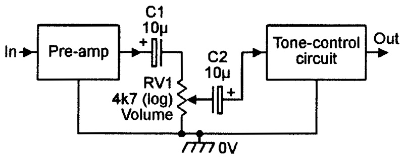
FIGURE 11.
TONE CONTROL CIRCUITS
A tone control network lets the user alter the frequency response of the amplifier system to suit a personal mood or requirement. Simple tone control networks consist of collections of C-R filters, through which the audio signals are passed — these networks are passive, and cause some degree of signal attenuation. Figure 12 shows the practical circuit of a passive tone control network that gives about 20dB of signal attenuation when the bass and treble controls are in the flat position, and gives maximum bass and treble boost and cut values of about 20dB relative to the flat performance. The input to this circuit can be taken from the circuit’s volume control, and the output can be fed to the input of the main power amplifier.
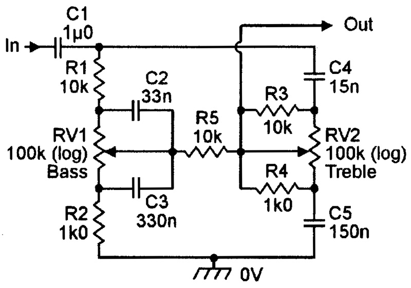
FIGURE 12.
The basic action of the Figure 12 tone control network can be understood with the help of Figures 13 and 14, which show (a) the basic circuit and its equivalents under (b) boost, (c) cut, and (d) flat conditions of the bass and treble tone control networks, respectively. Brief explanations of these two diagrams are as follows. In the Figure 13 bass control diagram, C1 is shorted out via RV1 when RV1 is in the maximum boost position, to give the equivalent circuit of (b), which gives only slight bass attenuation. When RV1 is in the maximum cut position, it shorts out C2, to give the equivalent circuit of (c), which gives roughly 40dB of bass attenuation. Finally, when RV1 is in the flat position, it gives the equivalent circuit of (d), which gives about 20dB of signal attenuation at all frequencies. Thus, this bass control circuit gives a maximum of about 20dB of bass boost or cut relative to the flat signals.
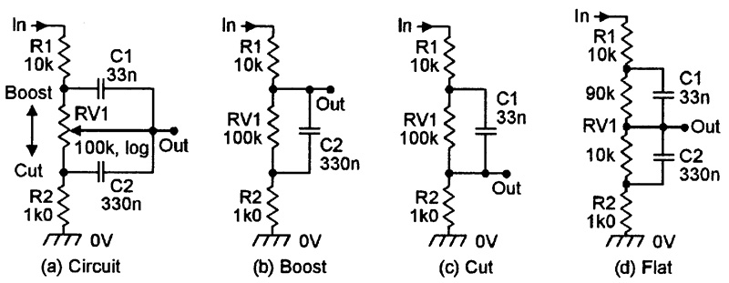
FIGURE 13.
In the Figure 14 treble control diagram, R1 is shorted out when RV1 is in the maximum boost position, to give the equivalent circuit of (b), and R2 is shorted out when RV1 is in the maximum cut position, to give the equivalent circuit of (c). When RV1 is set to the flat position, the circuit equivalent is that of (d), which gives about 20dB of signal attenuation at all frequencies. The net result is that this treble control circuit gives a maximum of about 20dB of treble boost or cut relative to the flat signals.
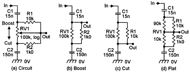
FIGURE 14.
A passive tone control network of the basic type described above can easily be wired into the feedback path of a transistor amplifier so that the system gives an overall signal gain (rather than attenuation) when its controls are in the flat position. Figure 15 shows a practical example of an active tone control circuit of this type. In this particular example, the design uses a modified version of the basic Figure 12 tone control circuit, which enables the tone-control circuit to use three (rather than four) tone-control capacitors.
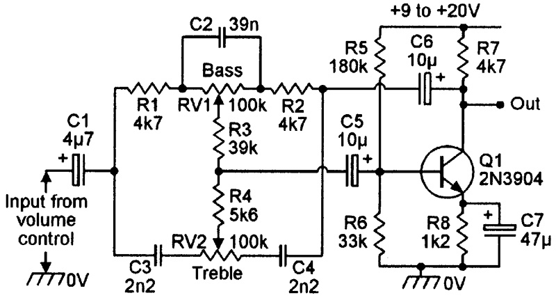
FIGURE 15.
AUDIO MIXER CIRCUITS
One useful gadget that can be fitted in the area of the volume/tone-control section of an audio amplifier is a multi-channel audio mixer, which enables several different audio signals to be mixed together to form a single composite output signal. This can be useful in, for example, enabling the user to hear the emergency sounds of a front-door or baby-room microphone, etc., while listening to normal entertainment sources.
Figure 16 shows an example of a simple three-channel audio mixer that gives unity gain between the output and each input. Each input channel comprises a single 100nF capacitor (C1) and 100K resistor (R1), and presents an input impedance of 100K. The circuit can be given any desired number of input channels by simply adding more C1 and R1 components. In use, the mixer should be placed between the output of the tone-control circuitry and the input of the main power amplifier, with one input taken from the tone-control output and the others taken from the desired signal sources.
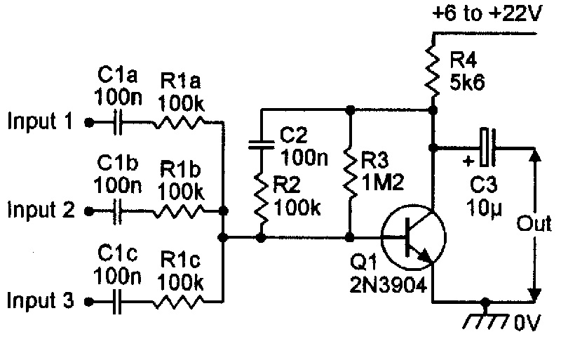
FIGURE 16.
Figure 17 shows a simple way of adding independent volume and on/off control to any desired number of input channels of the basic Figure 16 audio mixer circuit — RV1 controls the volume, and S1 provides the on/off function.
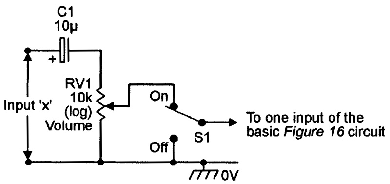
FIGURE 17.
SCRATCH/RUMBLE FILTERS
A common annoyance when playing old records/disks is that of scratch and/or rumble sounds. The scratch noises are mainly high-frequency (greater than 10 KHz) sounds picked up from the disk surface, and the rumbles are low-frequency (less than 50 Hz) sounds that are mostly caused by slow variations in motor-drive speed. Each of these noises can be greatly reduced or eliminated by passing the player’s audio signals through a filter that rejects troublesome parts of the audio spectrum. Figures 18 and 19 show suitable circuits.
The high-pass rumble filter in Figure 18 gives unity voltage gain to signals above 50 Hz, but gives 12dB per octave rejection to those below this value, i.e., it gives 40dB of attenuation at 5 Hz, etc. Emitter-follower Q1 is biased at half-supply volts from the R1-R2-C3 low-impedance point, but has negative feedback applied via the R3-C2-C1-R4 filter network. The circuit’s frequency turnover point can be altered by changing the C1-C2 values (which must be equal). Thus, if the C1-C2 values are halved (to 110nF), the turn-over frequency doubles (to 100 Hz), etc.
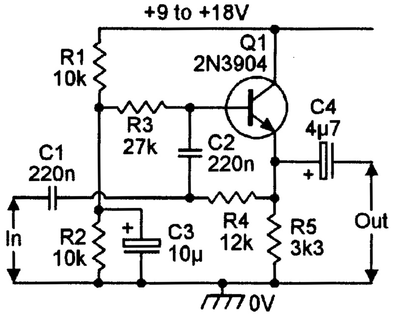
FIGURE 18.
The low-pass scratch filter in Figure 19 gives unity voltage gain to signals below 10 KHz, but gives 12dB per octave rejection to those above this value. This circuit is similar to that in Figure 18, except that the positions of the main filter network components are transposed. The circuit’s turn-over frequency can be altered by changing the C2-R4 values; e.g., values of 3.3nF give a frequency of 7.5 KHz.
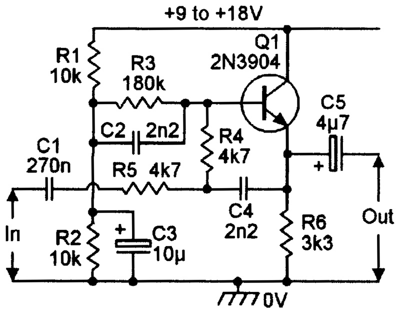
FIGURE 19.
The Figure 18 and 19 circuits can be combined, to make a composite scratch and rumble filter, by connecting the output of the high-pass filter to the input of the low-pass filter. If desired, the filters can be provided with bypass switches, enabling them to be easily switched in and out of circuit, by using the connections shown in Figure 20.
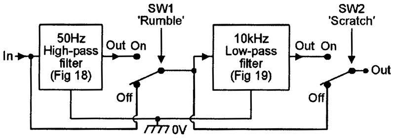
FIGURE 20.
Note that if the Figure 18 and 19 designs are built as a single unit, a few components can be saved by making the R1-R2-C3 biasing network common to both circuits. NV

