Could someone explain in simple terms how an AMP clamp works? Does it have a transformer in it or Hall-effect sensors or similar?
#12172
Kevin Champion
Cleveland, OH
Please log in to post an answer.
Answers
There are two major types of clamp on current meters. The AC type is a transformer; the wire in the clamp is the primary, the secondary is internal and is normally 1000 turns. If you are measuring 100 amps the secondary output will be 100 mA. The other type measures DC and could be calibrated for AC. The DC type uses a hall-effect or similar sensor. Amazon lists an AC/DC meter for $39.
Russell Kincaid
Milford, NH
Most clamp-on ammeters use a transformer located inside the body of the meter to step-up the measured current to a value which the unit can use.
Jeffrey Massey
Columbia
The common AC current meters use a transformer to measure the current. The “clamp” is the core for that transformer, and it is opened to go around the AC wire as it becomes the one-turn primary. There are simple components to scale the multi-turn secondary current down for the correct reading, either analog or digital. The digital part uses its own circuit to convert the measurement to its display.
A DC current meter cannot use the same transformer method, so it uses the Hall device that converts a magnetic field to a resistance, and the internal components convert that resistance to a reading, analog or digital.
Raymond Ramirez
Bayamon, PR
You are on the right track. The ones that measure AC use a pickup coil, and the ones that measure DC use a Hall effect sensor.
Chip Veres
Miami, FL
An AMP clamp is a transformer having a one-turn primary (the conductor carrying the current to be measured) and a multi-turn secondary (to feed the measuring instrument).
Being a transformer, it can only be used to measure alternating current. Be aware of its measurement rating, because too much current can saturate the clamp, resulting in inaccurate readings.
The clamp is rated for sinusoidal currents: measurements of non-sinusoidal current is best done with a true-RMS instrument connected to the clamp secondary winding.
Currents small relative to the capability of the clamp can be measured by passing the conductor through the clamp multiple times and dividing the measured value by the number of turns.
Peter A. Goodwin
Rockport, MA
AC amp clamps use a current transformer. The clamp is a laminated iron ring with a coil of wire wound around it. The alternating current in a powered AC line induces a magnetic flux in the clamp’s ring which the attached coil picks up via electromagnetic induction. That induced signal is fed to an amplifier who’s output is rectified and filtered and the resulting averaged (i.e. RMS) DC voltage is fed to the meter’s measuring circuit. The typical conversion is 1A AC = 1V DC on the meter.
DC clamps use Hall Effect sensors. As I understand them, the construction is similar to AC clamps, except an exciter coil is attached to the iron ring to pre-energize the ring with a specific frequency/voltage, which the Hall Effect circuitry sees as a zero level. DC current flowing through the clamp creates a magnetic field which alters that excite signal, which in turn changes the signal the Hall Effect sensor sees, which causes the Hall Effect detector circuit to output a voltage (positive or negative) proportionate to the current flowing in the measured conductor. Like the AC clamp, that detected signal is fed to an amplifier which outputs a DC level which is fed to the meter’s measuring circuit with a similar conversion scale (i.e. 1A DC = 1V DC on the meter).
As you’re aware, amp clamps are an EXTREMELY SAFE method of measuring high current (i.e. 10’s and 100’s of amps) in powered circuits because you don’t have to break any wires for making the measurement. HOWEVER, because their resolution is typically between 100 mA (0.1A) and 1A (due to the limitations of the magnetic detection circuitry), amp clamp’s use is limited to measuring power lines connected to large devices (i.e. pump motors) that naturally consume large amounts of current in operation.
Ken Simmons
Auburn, WA
Is there an emulator for a Digital Equipment Corporation’s VAX VMS 4.7 machine, either running on an SBC (Single Board Computer), or possibly an image that can run as a virtual machine in VMWare or something similar?
I want to create a four-node VAX cluster like the one I used to work on, and would love to see it sitting on my desk as a stack of Raspberry Pi boards.
#12171
Troy Thoele
Huntsville, TX
Please log in to post an answer.
Answers
Consider looking at SimH. It has a network-capable VAX Simulator. It is available in source code form (say, if you wanted to run it under Linux on an SBC), and also as a windows executable (you would not have to have use a virtual machine). Visit http://simh.trailing-edge.com/.
Jay Jaeger
Madison, WI
I picked up a CrownDC150a power amp at a garage sale. When I tested it on my bench, one side is rather distorted but then clears up once the amp warms up, making it hard to trace. Is this a common problem with these amps? Any troubleshooting tips are appreciated.
#11175
Rich Wortman
Kankakee, IL
Please log in to post an answer.
Answers
Crowns are generally great amps, very few issues. My guess is you have a cracked or weak solder joint someplace, perhaps in the power stage, that makes better contact once things get hot and expand. It might also be a bad cap somewhere, but that seems less likely to me.
Ralph Hipps
CA
You mention the model is DC150A. Crown does not list that model but does have a D-150 and D-150AII listed.
Service info is here https://www.crownaudio.com/en/products/d-series.
The symptom you mention could be crossover distortion in the output stage due to an out of spec bias voltage (very low or non existent). As the amp warms up the bias voltage generator begins to function to some degree and the distortion becomes less. The bias voltage is designed to vary as the output stage temperature changes but should never fall to zero.
Connect an audio generator (1 KHz, variable 0 to about 2 V RMS sine wave) to the amps input and connect a suitable sized dummy load (8 ohm) resistor and oscilloscope to the output terminals. Power up the amp and observe the output sine wave for distortion at the zero crossing. Also look for a symmetrical sine wave amplitude. An offset step at the zero crossing is likely a bias problem.
A non symmetrical sine wave could be a power supply problem or output transistor problem. If the sine wave is clipped on the top (well before maximum output power is reached) but the zero crossing point seems ok then the bias may not be the issue. Rather, the power supply voltage could be too low or the distortion is being introduced at the input stage or possibly the VA (voltage amplifier) stage.
Erik von Seggern
Escondido, CA
One can often use a controlled burst of freeze spray to hit individual components once it has warmed up. Hitting resistors or capacitors, or even solder connections may reveal the culprit.
George Kaczowka
York, ME
I have a generator and some old but useable communications gear that I’d like to donate to the hurricane victims in Puerto Rico. Since it's somewaht specialized gear, how does one go about getting it into the right hands so it will do some good? Is there some sort of national clearing house or maybe ham volunteer groups?
#11174
Randy Argueta
Danville, VA
Please log in to post an answer.
I have a submersible well water pump motor that is suspended down-hole on about 100 ft of plastic pipe. Whenever the pump starts, it torques the pipe and I fear it may eventually cause leaks/breaks. Is there a way to soft-start this motor? It's a three-phase 3HP unit.
#11173
Mario Rivera
Buda, TX
Please log in to post an answer.
Answers
Motor soft-starters have become so common that there is even a Wikipedia article about them. Just look in the catalog of the nearest industrial electric supply and buy the size you need.
Chip Veres
Miami, FL
The solution here is a devise called a torque arrestor. Google "well pump torque arrestor" for more information.
Bill van Dijk
Carp, ON CANADA
I recommend a commercial soft-start 3-phase motor controller such as one in the ABB Softstarter family. You can look through a catalog and technical information here: [url=http://new.abb.com/low-voltage/products/softstarters]http://new.abb.com/low-voltage/products/softstarters[/url]. DO NOT try to build one yourself. Experimenting with three-phase line power can lead to problems that cost more than a commercial controller. Another suggestion: Connect a stainless-steel line to your pump to make it easy to hoist. If you try to lift it via the pipe or the electrical cord the pump could separate and leave you in a hole, literally. (I have no connection with ABB.)
Jon Titus
Herriman, UT
I bought a 110V AC line isolation transformer to use with some old two-wire radios to see if I could reduce the AC hum in the audio. The audio is great, but now I’m bothered by the hum of the isolation transformer.
I read that it’s probably due to the transformer interacting with the metal enclosure. Should I remove the transformer from the metal enclosure and put it in a plastic one?
#11172
Thomas Hering
Savannah, GA
Please log in to post an answer.
Answers
The transformer hum is due to loose steel laminations in the transformer core. The alternating magnetic field (60 Hz) sets up a vibration within the core that can also be considerably amplified by the enclosure, if the enclosure and transformer mounting happen to resonate.
Your enclosure material is not the actual problem. Try placing the transformer on rubber isolation cushions to isolate it from the chassis/enclosure. Rubber grommets work well for this. This may reduce the hum, however, this will not address the loose laminations within the transformer and it will still make some hum sound. I don’t think much can be done about that except replacing the transformer.
Erik
Escondido, CA
It could be the case, but it also could be the laminations in the transformer core itself rattling after warm-up. Remove it from the case and make a trial run with the bare transformer sitting on a insulated surface (plywood) to find out. Or wear headphones and ignore the noise.
Chip Veres
Miami, FL
Line-frequency transformers always hum because their core is made of laminated steel. Hum is more pronounced in inexpensive transformers where lower-grade steel is used and it is driven further into saturation on each alternating-current half-cycle. The hum that you’re experiencing is most likely acoustically coupled to the transformer enclosure into or onto which it is mounted.
Try to isolate the mechanical coupling — e.g., use rubber grommets around the mounting hardware.
Peter Goodwin
Rockport, MA
I’d like to have continuous variable control of the motor in my bench vibrator/polisher. It has a DC (not AC!) motor that is rated at 90 VDC with a power supply that delivers 10 amps. I prefer to build something myself. Anyone have some design tips, or better yet, a schematic?
#11171
Robert Browning
Boston, MA
Please log in to post an answer.
Answers
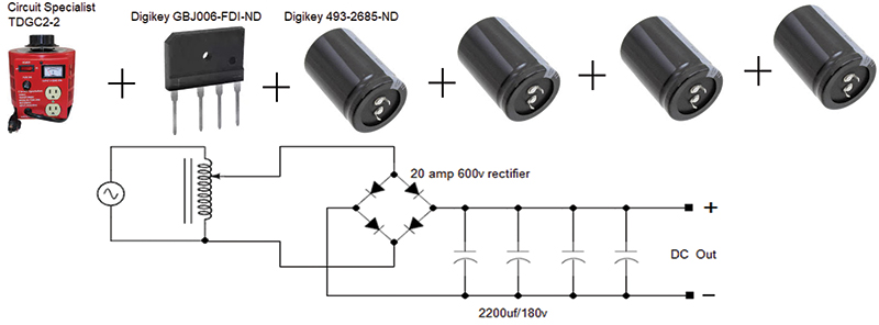
What about using a variac with a standard full wave rectifier and large filter capacitors? The schematic lists several commercial components.
Several things to mention before any attempt at construction.
- Be aware that most variacs are not fully isolated, meaning the neutral on the mains supply is connected to the neutral on the output.
- Mechanical stops will need to be implemented on the control dial as not to exceed a 90 volt DC output and most likely on the low end to prevent the motor from stalling.
Steve Ghioto
Atlantoc Beach, FL
Here is the "wrong" answer to the problem: Harbor Freight sells a Router Speed Control for $20. Plug it in between the wall outlet and your tool. See if it does what you want. If not, take it back and they will give you your money back.
Chip Veres
Miami, FL
I’m torn between using 3.3 and 5.0 volt components on my microcontroller projects. Many people seem to be moving to 3.3V, but components don’t seem to be as readily available as 5.0V components. What are the advantages and disadvantages of each?
#10174
Tony Sigler
New Brunswick, NJ
Please log in to post an answer.
Answers
Why switch when you can easily “translate” or convert 3.3V logic signals to 5V logic signals, and vice versa? Sparkfun electronics sells small boards with level-conversion devices ready to go. I prefer Texas Instruments SN74LVC4245 24-pin small-outline IC (SOIC) devices because they can translate eight signals independent of each other.
You’ll need two of these ICs, one for 3.3V to 5V logic, and another for 5V to 3.3V logic. You can mount these SMT ICs on Schmartboard SOIC-to-DIP adapters. Other suppliers offer similar products but I find the Schmartboard adapters easiest to solder.
Jon Titus
Herriman, UT
In my view, that is not really an up front issue. If I want to build a logic circuit, I have an idea of what I want it to do. Than I start looking for the required parts, making a list of what parts would work, and some of the basic specs such as its operating voltage, cost, footprint, availability, etc.
Sometimes most of the required parts are only available in 3.3V, and the decision is made. Sometimes they are available in 3.3 and 5V, but the 3.3V version is some difficult package I can’t solder. Sometimes I can’t find all required parts in the same voltage, and I end up implementing a logic level shifter, usually simple to build with 2 transistors and a couple of resistors.
Point I’m trying to make is that the decision to go with 3.3 or 5V is usually dictated by the design, not a starting point.
Bill van Dijk
Ottawa, Canada
I recently did a “tear-down” of a Baofeng BL-8 battery eliminator (for use with a UV82 dual-band tranceiver; see www.hamguyparts.com, articles). The tear-down revealed that the eight volt battery eliminator actually used 2X L7808CV TO-220 voltage regulators connected pin for pin in parallel, which is somewhat unconventional.
Both regularors were mounted to a common small (20 x 34 x 1.8 mm) aluminum heatsink and all enclosed within the plastic housing which was sized to resemble the battery it was replacing.
In the ideal case, each regulator would carry 1/2 the total maximum current taken by the transceiver, which is approx. 0.775 amps. Each regulator produces a nominal 8.0 volt DC output and has to dissipate approx 4.6 watts of heat. The thermal resistance of the TO220 package is 5°C per watt, junction to case (or mounting base).
They are mounted dry, which adds another 1°C per watt for mounting the base to the heatsink.
Q1: What is the temperature rise in the aluminum plate?
Q2: Since there is no direct path to air, what further temperature rise may take place inside the plastic housing?
#10173
Don Dorward
Pickering, ONT Canada
Please log in to post an answer.
Answers
I searched my hard disc and found a chart for thermal resistance vs. heat sink area for a 1.5mm thick heat sink. 1.8mm is not much different from 1.5mm so I will use that. This chart ends at 500 sq. cm. so I will extend the line and estimate that the thermal resistance is 2 deg C per watt. I am also assuming the thermal resistance is in deg C/watt since it is not otherwise labeled.
Since the dissipation is 4.6 watts per TO220 and there are two of them, the power to the heat sink is 9.2 watts. The heat sink area is 34X20=680 sq. mm. The temperature rise in the heat sink is: 2 deg C/watt X 9.2 watts = 18.4 deg C. The temperature rise to the junction of the TO220 is: 6 deg/watt X 4.6 watts = 27.6 deg C. Adding these together, the junction of the TO220 will be 46 deg C above the heat sink temperature which will be above the ambient of nominal 25 deg C.
It is not possible to estimate the further rise of the heat sink due to lack of air circulation without more information such as size of the enclosure, thickness of the plastic, thermal resistance of the plastic, etcetera.
Russell Kincaid
Milford, NH
My roommate keeps a piece of masking tape over the lens of the camera on his laptop. I think he’s paranoid; he says he’s being safe. I’d love opinions about which one of us is right.
#10172
Neil Nelson
Elkhart, IN
Please log in to post an answer.
Answers
Laptops, by virtue of their portability, are far more likely to be infected by malware than other computers. Cafes with "free" wireless are perfect networks for dark-side hackers. Once they get their "kung fu" into the system, they essentially own it. Also, remember that the NSA has the manufacturers bake in the ability to turn on the microphone of a cellular phone, even while it's turned off. The government doesn't deny this. That's why almost all of the batteries are now glued into smartphones - removing the battery would prevent it. We would be naive to assume it's significantly different for webcams. Think of the tape is a low-tech low-priced protection method of last resort. We should all do the same.
Roger Sudol
West Orange
He is. The camera can be disabled under the operating system since it uses a software driver to convert the signals into data. Just have him search for that driver file (visit the help page of the O/S provider) and rename it, move it, or delete it (ignore any O/S attempts to replace the driver). If he sells the laptop, a new O/S install will revive the camera driver.
Raymond Ramirez
Bayamon
I hate to say it, but your roommate is right.
As someone who builds gaming computers for a living, I can tell you that any computer that is connected to the internet, can be subjected to some sort of unauthorized access. That’s why we have things like Anti-Virus, Firewalls and other protective programs.
With that being said, your camera can very well be accessed from the outside. Your roommates tape solution is common and works effectively to keep unwanted eyes from seeing what you’re doing. However, you should know that if someone has access to your camera, they have access to your hard drives as well!
You can make it harder for someone to access your Network by having a WPK Passcode instead of a WEP Passcode on your router, and setting up a secondary computer as a stand-alone firewall.
Hopefully I have answered your camera question.
Robert Nelson
Hurricane, UT
As they say, “Just because you a paranoid, doesn’t mean that they aren’t out to get you.”
Actually, like your roommate, I also keep tape over my camera when I don’t intend on using it. I’m not actually as worried about someone hacking into it as I am about accidentally turning it on without knowing. It could be really embarrassing to find out later that your cam was on and someone was watching via Skype or something similar without you knowing.
Having someone hack into the cam is certainly possible. But user error is probably more likely. Either way, why not be safe and blind the camera when not needed.
Ray Matthews
Freeport, IL