My desk fan has a three-position switch: HI/OFF/LOW. I would like to convert the fan to variable speed. Will a simple lamp dimmer work for this purpose? If so, what winding of the motor do I connect it to? High or low?
#10161
Michael Walczak
St Helens, OR
Please log in to post an answer.
Answers
Danger Danger! The typical lamp dimmer is not compatible with the typical cheap fan motor. There are good articles on the web as to why. Look up shaded pole speed control and see why. That said, I find that box fan motors tend to be OK with better (triac based) motor speed controllers, such as sold by Harbor Freight and on eBay. On a shaded pole motor of a typical cheap fan, overheating the motor is possible.
Jim Lacenski
Bellevue WA
Just connect the new dimmer to the High contact of the switch.
M.Herman
LaQuinta, CA
Please do not even think of using a simple lamp dimmer for this!
Lamp dimmers are for incandescent (filament) bulbs only, not inductive motor (AC or DC) loads and will likely cause a fire! A lamp dimmer connected to a ceiling fan caused such a fire, nearly burning my neighbor’s house down! Don’t do it.
The easiest, cheapest and safest solution is readily available from Harbor Freight Tools. Item 43060 is a “Router Speed Control” and works great with inductive AC or DC motors up to 15 Amps (120VAC). I have several and use them to vary the speed of many tools, not just my router. Costing about $15 a piece, I use this controller with my 5-speed wood drill press (when drilling soft metals that require slower speeds); with Harbor Freight’s largest “hurricane” fan (which also has a HI/MED/LOW/OFF switch); and other AC powered fixed speed tools.
Equipped with a 15 Amp 3AG type fuse and a 3-prong receptacle, this lightweight controller is hard to beat and much safer to use.
BGoodWill
Rahway, NJ
Good news and bad news: A light dimmer will in fact slow down a fan motor. However, the motor will make a horrible buzz. Look for a device called a Quiet Fan Speed Control. This is just a tapped inductor with a switch to cut in more or less of the coil. You can tell you have one if the speed control is a switch rather than a pot. Given the multiple speed taps plus the original high-medium-low, you should find a speed that suits.
Chip Veres
Miami, FL
It should work just fine. Wire it to the high winding. I did this myself to a box fan 43 years ago and it is still running.
Jerry McCarty
Jackson, MI
I’m retired and re-learning electronics. I am confused about the differences between MOSFET and “regular” transistors. Is there a rule of thumb as to when/where/why you would use one over the other?
#9164
Arthur Bergerson
Latham, NY
Please log in to post an answer.
Answers
Traditionally, MOSFETS were used for small-signal amplifiers and mixers, particularly at high frequencies. High currents or voltages would easily burn them out. Today there are power MOSFETS but they aren't very fast. So the existing MOSFETS tend to fall in two families: Fast but fragile, or strong but slow. Kind of like people.
Chip Veres
Miami, FL
I have a box of cassette audio tapes that I want to convert to MP3 format. What's the simplest way to do it? I have a Windows 10 PC and a Nakamichi CR-2A cassette deck.
#9163
Samantha Costa
Boise, ID
Please log in to post an answer.
Answers
As for this, maybe you could also take a try of DRmare Audio Recorder Software. It is a tool that can help you record the audios on your computer. That is to say, you need to play your cassette audios on your computer and then use DRmare program to record and convert those audios in MP3 audio format. Hope this tool will help you.
Kasssie Jane
USA
Thre is a very good little box made just for transferring LP's and CD's to MP3 or wave format. It's made by DAK and costs $69.90. See the link: www.dak.com/reviews/2021story.cfm
The box accepts stereo input from any source (including a microphone), provides for balance and loudness adjustment, digitizes it according to the resolution you want, and prepares a file for a CD. You can name the flie and see the audio as it is played. This is especially useful in that you can ensure that the signal is not being clipped. One can then run the file(s) through a hiss and click reduction program, which is especially good as it is based on an algorithm rather than just clipping spikes. Thus, it works on low amplitude as well as high amplitude signals.
The latest software also has a feature which will automatically take out the large gap one may have between sides of tapes or LPs, leaving only, say 3 seconds. I have found the whole process very satisfactory, though time consuming, as one must, of course, pay a certain amount of attention to whether the tape or LP is finished when doing the conversion. The ideal thing is to have two screens on your computer so you can keep your eye on the conversion process while doing other work on the other screen.
I have recently downsized and moved to a retirement home. I will never use the thing again. I can't find the software disk, though I have the program on my computer, of course. I would be happy to give you the box. DAK might sell you the latest version of the software.
John Drake
Ann Arbor, MI
Quite easy to do. You need to get a cable to go from the RCA jacks on your cassette deck to a stereo mini plug to go into your PC. Very common, but if you can't find one, then Amazon has them. Dynex A20420 and many others. For your purposes practically anything will do.
Then download Audacity, which in my humble opinion is the best audio editing program out there, especially since it is free. Go to www.audacityteam.org for the details. For MP3 export, you'll also need something called LAME, available on the Audacity site. Play your tapes into Audacity, then export them either as single songs-per-file or entire sides. For that matter, you can capture both sides of the tape, use Audacity to remove the dead areas that occur while changing sides. Or if you only like a couple of the songs, just copy-and-paste what you want.
Jerry McCarty
via email
If you don't need the absolute best in quality, the easiest way is to simply plug the line out from your cassette machine into the line in on your sound card. Most PCs/sound cards come with at least rudimentary software, or you can download Audacity, which is what I use. You will most likely need a stereo RCA to mini jack adapter, which are inexpensive, and available at RadioShack among other places. If you want a better quality conversion, you can get a phono/line in USB device. Make sure it supports both phono and line in. I purchased an NAD Digital Phono/USB Pream PP4 for transcribing my vinyl.
Jay Jaeger
Madison, Wi
Assuming the cassette deck has LINE LEVEL outputs, use a stereo RCA-F to stereo 1/8" (3.5mm) adapter to directly feed the "LINE IN" (BLUE) jack on your motherboard. You'll then need a utility, like WIndows' "Sound Recorder". Load the tape into your recorder, start the recording utility, then start your tape deck. The file will be saved into, I believe, .WAV (wave) audio files, which you can convert to .MPG for use.
You can download Sound Recorder for Windows 10 from Microsoft. I suggest visiting sourceforge.net and perusing the open-source offerings ("Audacity" seems to be The Standard for audio recording).
Ken Simmons
Auburn, MI
A patch cable from the line output of the cassette deck to the line input of the computer. Should be available wherever you get stereo stuff, probably including Walmart.
Chip Veres
Miami, FL
Here are a couple of ways of recording your tapes.
After connecting your cassette deck to your sound card's line input and adjusting the input level on Control Panel, you can record the tapes with software. I use SoundForge 11 Pro. Unfortunately, this costs a few hundred dollars.
Another option is iZotope's line of products, but again, these are far from free. If you want open source software, download LAME. A friend of mine loves it. LAME is distributed as C source code only so you will need a C compiler. You can download GNU GCC compiler and install that.
All of these software solutions enable you to correct any audio problems after recording and save the corrected recordings in various formats. I use SoundForge to record 78 RPM records — not the 33 vinyls of the 1950s to present, but the shellac discs from 1895 to 1940s and on to 1954. The software removes ticks and pops and equalizes the frequency response appropriately.
Jerry Cogswell
Eureka, MT
Easiest thing to do would be to get a cable that will go between your tape deck and the computer. Usually (please check your connections) a dual male RCA plug to male 1/8" stereo plug will work. You can then plug this into your line in jack on your computer, and the line out jacks on your tape deck and get free software like Audacity to do the recording.
Brian Joseph
Libertyville, IL
I recently discovered a cassette that my now-deceased father had recorded in 1998. He was whistling and playing a handmade wooden flute and I wanted to provide that to friends and family. I found the audio editing software "Audacity" after a search and it has worked well for me. It is free, open-source and will run on Windows, Mac, and Linux. You can download it at www.audacityteam.org. The documentation can be found at www.audacityteam.org/help/documentation. Very informative tutorials start at http://manual.audacityteam.org/#tutorials.
The first important part to figure out is how to connect the cassette deck to your computer. The whole process is explained well at http://manual.audacityteam.org/man/tutorial_your_first_recording.html and http://manual.audacityteam.org/man/how_to_connect_your_equipment.html. You will then, in a nutshell:
- create a project
- capture the raw audio
- save the audio as an uncompressed .wav file
- edit your audio if you wish
- and finally export to .mp3
Note that: "Unfortunately, the algorithm to encode or create MP3 files is patented and Audacity would not be able to include an MP3 exporting algorithm without either charging a fee or potentially violating copyright law in some countries. As a compromise, Audacity comes with the ability to use other MP3 encoders, which you must download separately. It is up to you to make sure you are in compliance with any licensing restrictions imposed by MP3 encoders. To install LAME, see http://manual.audacityteam.org/man/faq_installation_and_plug_ins.html#lame".
I am editing my approximately 25 minutes of audio in the hopes of creating a CD. The tutorials explain that as well if you wish to try. Good luck.
Barry Murrill
Chandler, AZ
I am looking to experiment with “ultra capacitors” as a replacement for AA batteries. Is this possible to do and, if so, what kind of capacitors would be a good place to start?
#9162
Glen Ross
Marietta, GA
Please log in to post an answer.
Answers
The short answer is NO. The main function of Ultra caps is for TEMPORARY backup of memory type devices (i.e., clocks in DVD players) during brief (i.e., less than a day) power outages. They are NOT suitable, nor designed, to replace batteries simply because, as they are electrolytic capacitors, they need recharging when their stored energy is depleted. Also, they're not really designed for current loads greater than a couple hundred microamps. This subject has come up a few times in the past couple of years and I believe N&V had an article comparing ultra caps to batteries (primary and rechargeable).
Ken Simmons
Auburn, MI
This is only practical when the current draw is very low. A coulomb is one amp-second. By definition a one-Farad capacitor charged to five volts can deliver five coulombs. A single AA battery can deliver at least 1350 coulombs. This is because the material of the battery is consumed when it is delivering current. The capacitor isn't consumed, it's just a tank for electricity. About the only practical use of a small ultracapacitor is to maintain a CMOS memory while the set is unplugged.
Chip Veres
Miami, FL
I have done this. I'm going to put the conclusion right up front for those not interested in reading the rest of this. Given the present prices for AA batteries and ultracapacitors, it makes no economic sense to do this at this time. But I rarely let such considerations stop me from having fun.
First some theoretical analysis
Ultracapacitors and AA batteries both store energy. How much? For a capacitor, the energy stored is 1/2 * C * V^2 where C is the capacitance in Farads, and V is the voltage across the cap in Volts. One farad-volt^2 is one Joule of energy. I take a Maxwell Technologies BCAP1500 P270 as an example. This is a 1,500 Farad, 2.7 Volt capacitor. It is cylindrical in shape and with a diameter of 2.4 inches and a height of 4.5 inches. Volume = 20.36 cubic inches. It is a little smaller than a soda can. When charged to 1.5 Volts it has 0.5*1500*1.5*1.5 = 1,687 Joules of energy. When charged to it's maximum 2.7 Volts is has 5,467 Joules. These cost $59.20 at Digi-Key in quantity of 1.
Batteries are not usually rated by the energy they store, but this can be figured out. I take a RadioShack AA NiMH rechargeable battery as an example. These are cylindrical in shape with a diameter of 0.55 inches and a height of 2 inches. Volume = 0.5 cubic inches. Batteries are rated in Amp-hours. These are 2.5 Amp-Hours or 2500 mA-Hours. To equate this to an amount of energy, I enlist a theoretical load that draws 125 mA regardless of the voltage applied. One can make an actual load like this using a current source, but it must be able to work at these low voltages.
Starting fully charged, I run this for 20 Hours. I note that the average output voltage of the battery during the run is 1.2 Volts. I do the following calculations: Average output power = 1.2 Volts x 0.125 Amps = 150 mWatt. Energy used = .15 x 20 = 3 Watt-Hours. There are 3,600 Joules in one Watt-Hour so Energy used = 10,800 Joules. These batteries cost $19.95 for a set of four, so they are $5.00 each. Also note that a battery will hold its output voltage fairly steady until it is close to fully discharged. When using a capacitor, the output voltage will decrease in a linear fashion as current is drawn. For a capacitor i = C * dv/dt so dv/dt = i/C where i is current, C is capacitance in farads and dv/dt is the rate of change of voltage.
Using the above numbers if I start at 1.4 Volts (1,470 Joules in the capacitor) and I have to stop at 1.0 Volts (750 Joules left in the capacitor) because my "load" (a portable radio for example) will not work below 1.0 Volts, then I have only gotten 720 Joules out of the capacitor. If my "load" can operate without problems at 2.7 Volts, then between 2.7 volts and 1.0 volts I can get 4,717 Joules (86% of a full charge) from the capacitor per cycle.
One of the great disadvantages of a battery is that any rechargeable battery has a cycle limit. Battery manufacturers don't like to point this out but one can only charge and discharge a battery so many times before it losses its ability to hold a charge and has to be replaced. It depends on conditions but I have seen numbers between 300 to 1,000 cycles. Whether this is important depends on what you are doing. This is where a ultracapacitor can really shine. According to the Maxwell data sheet, one can cycle these ultracapacitors one million times and it will not lose more than 20% of its initial capacity.
In summary:
Battery Energy
- Stored 10,800 Joules
- Size 0.5 cubic inches
- Cost $5.00
- Lifetime up to 1,000 cycles
Ultracapacitor Energy
- Stored less than half of what a battery can store
- Size 40 times more space than a battery
- Cost Nearly 12 times more than a battery
- Lifetime One million cycles.
Not looking good for the ultracapacitors.
Now let's switch to discussing an actual experiment. I was in a local discount store when I found some "Floating Ball Solar Light" gadgets. As an impulse buy, I bought three of these things. These consist of a clear plastic ball about 6 inches in diameter. Inside this clear plastic ball is what I will call a solar lantern. This is a translucent cylinder about 2.5 inches tall and 1.75 inches in diameter with a plate at the top and a plate at the bottom. On top of the top plate is a small square solar cell 1.75 inches square. Below the bottom plate is a small compartment. At the very bottom of the sphere there is a small rubber gasket that actually covers a push-on-push-off button which allows one to turn these things off when not in use.
My wife thought these things were the cat's meow as they floated around the pool glowing softly in the evenings. They each had different colors of LEDs in them. Unfortunately they only lasted a few days until the internal batteries went dead and they stopped working and went in the junk box.
Two other notes, locating the on-off switch at the bottom, below the waterline was a bad idea as the gasket tended to leak. The outer sphere was actually two hemi-spheres that were glued together at the equator. This also tended to leak allowing rainwater in.
A few weeks later I took one and cut it apart. Inside is a single LED that illuminates the lantern. In the base is a small PCB with a single "glop top" IC. The battery leads were soldered to the terminals of a AAA battery. I unsoldered the leads and disposed of the old battery. I made some measurements. Under conditions of darkness, the LED draws about 10 mA. Under conditions of full sunlight the solar cell can produce 38 mA of current. On the surface, it would seem this should work.
I wired a 1500 Farad ultracapacitor to the battery leads and set the unit out in the sun for a day. The ultracapitor had about 1.4 volts on it which is enough to keep the LED glowing all night long. I can't leave the unit outdoors for a long term test because it is not waterproof in its present state. I can't put it back together like it was because the ultracapacitor is 40 times bigger than the battery it is replacing. I'm sure that like all electronic components, ultracapacitors will get smaller and cheaper over time, but they have a way to go to match batteries. I hate to buy batteries because I know they will go dead and have to be replaced in a few years at most. There is a strong psychological appeal to something that you can buy once and have it last for your whole lifetime.
If ultracapacitors down get down to a size where they would fit where existing batteries fit, then they might start to displace existing batteries. At present ultracapacitors are used in other applications.
Andy Haber
Fort Lauderdale, FL
My X-10 home automation gear has been reliable for years but just recently has become intermittent. Is there a way to test for what might be interfering with the operation?
#9161
Malcom Williams
Camden, NJ
Please log in to post an answer.
Answers
X-10 was developed back in the '70's as the first consumer power line carrier (PLC) home automation product. While newer and more robust systems are available, X10 remains popular due to its simplicity and low cost. Back in the '70's we didn't have the plethora of wall warts, PC/printer/monitor power supplies or CFL & LED bulbs, all of which tend to either absorb X10 signals or put noise on the power line or both!
All of these signal suckers and/or noise generators can swamp the X10 signal resulting in the problems you're experiencing. There are filters, amplifier/repeaters and couplers to resolve these issues and, I'm happy to report that, after over 30 years of using X10, I've been able to maintain reliable operation even in fairly large homes.
Before adding any of the above devices, the trick is to identify the source(s) of the problem. At the time the intermittent problem began, think about what changed in the house. A new TV, computer, monitor or phone/tablet charger? Conversion to CFL or LED bulbs? If any of those get a yes, try removing them and testing. Plug-in filters will help.
Does the problem only happen at certain times? For example, when my in-ground incandescent pool light burnt out I replaced it with an LED bulb. When it was on it generated sufficient noise to render X10 useless to a number of locations. The solution was to add a hash choke in series between the switched wire from the X10 module and the light. Problem solved.
Another very important consideration is coupling from one side of the power line to the other. As we all know, residential service consists of two 120 volt legs (L1 & L2) from the street transformer to the electrical panel where roughly half the circuits are served by each leg. Electric ovens, water heaters and central A/C units are connected to both legs to provide 240 volt service. If an X10 controller is plugged into an outlet on L1 and the lamp module is plugged into an outlet on L2, the signal needs to find a bridge to get from one leg to the other. That bridge can be a 240 volt appliance, if it's on, or the street transformer itself - a long run that attenuates the signal.
The solution is to use a coupler at the electrical panel to provide a reliable path for the signal to reach every circuit. The very best solution that will overcome a multitude of problems is the installation of an XTB-IIR which is both a coupler and X-10 signal amplifier. It's available both as a kit or fully assembled from www.jvde.us. Building the kit is within the capabilities of most Nuts & Volts readers. That site offers a number of solutions and some great tutorials on X10 troubleshooting. I've been using both their site as a resource and their products for many years with great success.
Bruce Robin
Naples, FL
I was having the same problem, with flakier and flakier performance. Some online research indicates that the problem is the result of the ever-increasing number of AC power line operated digital devices we use, each of which can feed noise back into the power line, potentially causing problems for other devices.
To prevent this, AC power line connections use a lot of filtering components (inductors and bypass capacitors) to prevent the digital noise from traveling back into the AC power line, but the bypass capacitors essentially short circuit the 120 kHz X-10 signals so they can't reach the devices they are intended to control. It's time to switch to Z-wave or one of the other radio-based control systems.
Daniel Duncan
San Gabriel, CA
The X-10 protocol is passed at voltage zero, which makes it subject to other devices that operate at voltage zero. Did you add any electronic controls (lights, motor controller, etc) to your home? If you Google X-10 problems, you will get many possible solutions. Also, did you have any electrical work done at your house recently? If so look into the capacitor bridge to see if this helps. Also, look into possible noise sources (electric motors, SRC controls, etc.) as these may be producing sufficient noise to interfere with the X-10 signals.
Dave Bassett
FL
You can get a "Powerline Signal Analyzer" but they cost $$$$. What I found was after many years of using X10, it became unusable due to interference. Do you have any UPSs at your location? They can be causing interference. Smarthome has wire-in filters that will help as well as plug in ones.
Brian Joseph
Libertyville, IL
I would like to add a "rain detector" to my sprinkler system that would automatically disable the sprinklers. The system uses an old-style mechanical "dumb" timer. How about a simple circuit to do the job?
#8166
Gary Hunt
Southfield, MI
Please log in to post an answer.
Answers
You can buy a normally closed SPST switch containing a water absorbing material that expands when wet to open a microswitch. This is placed in between the common side of the valves and the return line. The switch can be adjusted to open after an appropriate amount of rain has fallen. They are sold by most sprinkler manufacturers in home improvement and hardware stores.
Horton Prather
Buford, GA
It has fallen to me to teach a short course on electronics for a summer camp program near our home. I would welcome suggestions for curriculum! The kids are ages 8-12.
#8167
Levi Coughlin
Dunmor, KY
Please log in to post an answer.
Answers
Summer is about over so this might be useful for next year but this is what I would teach kids if I had about a week to do it.
DC/AC:
- Batteries and LEDs
- Types of electricity:
- DC, AC line power
- Power Line Safety
- Tesla coil RF
Series and Parallel game:
- Lines on floor
- Switches
- Rules
- Leader
AC line safety:
- Overloads
- Wet areas
- Reducing power use with CFL and LED bulbs
Takeapart Day:
- VCRs
- DVD players
- Computers and hard drives
- Problems with TVs - High voltage breaking glass
- Dangers of Micowave ovens and how to avoid them with proper supervision
The series and parallel game is played on a gym floor or grass area with lines laid out with painters tape or yarn and 4" nails. Use small rugs for batteries and lamps. Have kids to man the switches which are yarn sections with weights on the free ends.
The teacher yells out "switch one close' etc. then the switches move and the kids stationed along the "wires" move like electrons if the circuit is complete. Do a short circuit too where the kids have to move quickly and the teacher breaks the circuit and yells stop/sit down. This comes last followed by a comment and question time. This is modeled after the on stage demos that are part of Harvard's famous CS 50 class.
Have a local fire official do the line voltage safety lesson because they do this all the time.
Be sure to have tiny torx drivers for taking the super magnets out of hard drives.
I would like to see some guidelines for the takeapart day like:
- Unplug all wires rather than cut them
- Watch out for anything that has ink in it or on it and wear gloves while removing that part to the trash can
- Recycle everything not saved for parts.
I hope that you find this useful.
Dale Freye
via email
Recently, I too was asked to make an electronics presentation for the age group you mentioned. The library staff person referred to me as a docent, or lay presenter. The areas I get excited about would seem not to transfer well with this age group, so I needed help. Thankfully I was well-advised by the youth librarian who assisted me in creating and talking about very basic electrical experiments that she hoped would conclude with a hands-on soldering demonstration.
The first experiment employed a basic compass with five or so hand wound turns of 30ga. magnet wire circling it, powered with one AA battery. So why does this make the needle spin? Discussion about magnetism and electrical relationships. Can anyone envision a motor in this? (hold just one or two seconds to keep wire heating reduced)
The next presentation offered the very simplest circuit with a 'schematic' drawing representing the actual physical setup of a power source, wire connections, and a (lamp) load. Then a switch is added and drawn. Some discussion then about how current behaves and flows in this circuit.
The third presentation involved a zero center galvanometer (+ - .001A) those large clear classroom kind work great, the terminals connected to the winding of a nail or screw type electromagnet with a small magnet fluxing a field to induct current then swinging the needle both directions toward a basic conception of Alternating Current. Good time to mention diode rectification in the ensuing discussion.
The last was a very well-received LED yard light demonstration. A small solar panel, with an electronic control circuit connected to that zero center meter showing current direction both powering a white LED and charging a battery configured like this:
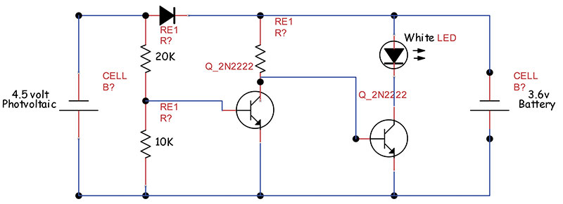
Schematic of Yard light
Just to the right of the White LED junction, between the 3.6volt battery, insert the zero-center galvanometer. A 3-4 ohm shunt between the + - meter connections offered dramatic visual current direction. Raise or lower shunt resistance as needed.
The kids responded well using objects and their hands to shade the photovoltaic panel watching the meter swing and the white LED turn on and off, either charging or emitting light with only a simple transistor circuit. As they were marveling I offered a brief description of the transistor operation in a schematic drawing describing the details of on-off (Schmitt) switching.
We DID have time to solder at the end. With a circuit board clamp at a comfortable angle, I used a 15 watt Weller with the LED lights, put my glasses on describing the need for a clean, tinned, tip and began soldering a hole-through PCB describing the process as I soldered each tiny pad. Would you like to try this? They all did, and I get teary in how excited they were when they completed their section of the many other pads. At the end of our class, the youth librarian shook my arm off in thanks, but I easily enjoyed it as much. It will be easier than you think. Have fun.
Michael Greenlee
via email
Suggestion depending on length of camp:
- Build an LED flashlight.
- LED flashlight with dimmer.
- Crystal radio.
- Crystal radio with one-transistor amplifier.
Chip Veres
Miami, FL
I want to extend my home alarm system to my garden shed. The shed has power but no simple way to get wire to it from the house. Is there a DIY wireless method to try?
#8165
Woodrow Young
Lima, OH
Please log in to post an answer.
Answers
Visit the "Alarms and Security" department of your local Home depot (or similar) and look for a "basic" wireless system with magnetic door/window transmitter sensors and a matching wireless receiver. Install the sensor(s) in your shed, set the transmitting "address" code(s), and install the batteries. Next, install the receiver near your existing Home Security system and run wires (i.e., #20 or #22 twin-lead) from the wireless receiver's "Trigger Out" (or similar "alarm contact" relay) connection to your main system's "External Trigger" (or similar) input and connect the receiver to power. NOTE: some wireless alarm receivers DO NOT have the "Trigger Out" capability - try to get one that does. Ensure the receiver has battery backup power if the main AC power is lost!
Next, test the shed system: put your main system in "test" mode. Trip one of the shed sensors and verify the wireless receiver activates the "Trigger Out" contact, which should trigger your main alarm via the "External Trigger" input (unless the receiver DOES NOT have the "Trigger Out" capability). Reset the system and repeat for the other shed sensors, verifying each tripped sensor activates the alarm (main system via "Trigger Out" or the wireless receiver alone). When you're satisfied all is working, take your main system out of "test" mode so the shed will be monitored.
NOTE: make sure you DISABLE the shed system before purposefully going to the shed or you'll get a false alarm! Also, ensure you RE-ENABLE the shed system when it's otherwise unoccupied.
Ken Simmons
Auburn, WA
Look at wireless remote doorbells, such as you can find at local hardware stores. They can be really cheap. Just re-work the doorbell button to the shed door sensor and then tap off the receiver (may require a bit of interface electonics, such as an optoisolator) in the house and feed to your alarm system.
Pete Lunt
Cary, NC
I have used the Wicked Devices 433Mhz system with Arduino controller when it is inconvenient to run a cable. The effective range is up to a couple of hundred feet. This unit has 4 channels that can be used and a lot of documentation & code is available on the internet.
The unit is also called Nanode Transmitter & Receiver . See www.wickeddevices.com for more information.
Gene Sellier
Fairhope, AL
There are a couple ways you can go with this:
1. Contact your alarm company and find out if the security panel in your home directly supports wireless devices. Most modern ones do. They would install a wireless door contact in the shed and program it to the alarm panel. Some security systems already have wireless built in or they may need to add a wireless receiver.As a bonus, you could add on a wireless keyfob to arm/disarm your house from the driveway. This would cost more than a DIY solution but they should be able to match up the proper equipment to make the setup as reliable as possible.
2. For a more DIY approach, Linear has available a wireless transmitter & receiver that could be integrated into any security system regardless of age. “Linear D-24A” is the transmitter and “Linear D-67” is the receiver.
The transmitter uses a battery and would still need to be connected to a set of door contacts on the shed door. The receiver wires directly to your security panel to power and one zone. You would want to use a spare zone on the security panel, but keep in mind, the zone may still need to be programmed by your alarm company. And if your security panel dials out to a monitoring company, your alarm company will need to add that zone to your account so that activation of that zone would alert the proper authorities.
Eric D. Bailey
Cecilton, MD
A simple cheap and dirty solution would be to use one of those wireless door bell setup’s that most hardware stores sell.
Place simple door (normally open) switches in parallel with the “door bell” switch mounted in the garden shed. Use a low current reed relay across the speaker output of the reciever in the house. Connect the normally open reed contacts to one of your alarm panel loops.
Wala, a cheap and dirty solution. You may need to add a latching relay of some sort.
Ray
Vancouver, Canada
Is there a simple way to determine how long a given circuit will run on a standard 9V battery?
#8164
Janet Patel
Amarillo, TX
Please log in to post an answer.
Answers
The load current you are drawing from your circuit and the time it will take to drain the battery is determined by the capacity of the nine volt battery you're using. How 'long' it will last as you expressed, is the circuit current your device circuit consumes. The average 9 volt battery capacity is given in milliamp hour rating -MAH. For common alkaline batteries it's about 500mah. Very simply 500 milliamps for one hour. This can be expressed differently but equally as half of one ampere for one hour. It's also is 25 mah for twenty hours, or 10mah for 50 hours. We simply divide 500 by your circuit's current load in milliamps, each milli-unit by the way is 1/1000 of an amp, to obtain the device load duration in actual time.
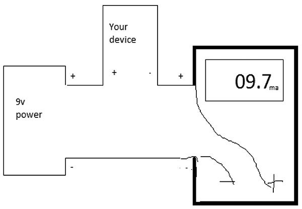
FIGURE 1
Unit measurement is important to understand realtionships in science and technology. You can find this load current draw - with your device, by using a digital multimeter -DMM, and power source like the actual battery, and some connectors. I like to use colored alligator jumpers, black to all marked negatives (see figure 1) and then all red to all positives. You don't have to color code this way but it helps to remember polarity. Set the meter to the high milliamp setting, most often 200 on low cost meters, just as long as it's well above your expected load. The current setting can be fragile for all meters since this test measurement might involve occasional large current, as in a SHORT or closed connective path which is 'shunted' through the meter's circuitry to express a current measurement. Thankfully it's fused. When I finish current settings by habit, I always reset my DVM or VOM to 20 volts or higher so I won't need to replace the fuses protecting the meter if I accidently measure too much current, on too low of a setting.
If you have a tech friend helping, you could also use their adjustable power supply. Set the battery voltage, hook up your device, (turn the device on!) and simply read the output current being used. Pretty much the easy way. Like you, I too like to know what current load various battery appliances use not only to predict run time, but also how big to the size up the battery if I wish. I use this setup alot.
I assumed for ease that the load you're device is using is steady and predictable. But maybe your load varies considerably. Time is constant, but the load fluxuates or turns on and off irregularly. You might proceed with some narlly math, but I'm more inclined to use our KILL-A-WATT type of household wattmeter - you have one don't you? Then plug in your power supply source set at 9 volts (but not from the battery) then read the watt-hour number over the time span you care to measure, then subtract the efficiency of the type of power supply your're using* from the total. I confess this is new for me. The Kill-A-Watt units are in 1/100 divisional units ie, amps, volts, except watt-hours is in tenths. Fair accuracy. I also have a WATTS UP like clone device that comprehensively continously measures DC power that is connected between a power source and it's load. Drone operators like these to monitor battery charging. Solar energy installations benefit from the detailed information they provide as well.
After experimenting with the AC wattmeter the Small switching xfmers show very small wattage unloaded. The estimated 10% loss isn't worth bothering to mention. Ferro-resonant laminated xfmers (wallwarts) on the other hand are hogs! an 800ma 12VDC unit drew 3.1 watts completely unloaded.
*The large and heavy laminate transformer wall-warts are about 60% efficient and the newer light weight and smaller high frequency switching transformers are up to 90% efficient. So in a very loose way you merely subtract the remaining percentage of the Wattmeter's total reading to fetch a general watthour reading. Length as you would say! Subtract from your total reading the percentage difference.
Michael Greenlee
via email
It depends on the device's current draw and its duty cycle, and on the battery type. For example, a 9-volt carbon-zinc (Leclanché), the "cheaper" batteries, are rated about 400 mA-hours, according to https://en.wikipedia.org/wiki/Nine-volt_battery.That theoretically means it could power a 1 mA load (e.g. 6,000 ohm resistor in series with a white LED dropping 3 V) for 400 hours, or a 10mA load (e.g. that same LED with a 600 ohm resistor) for 40 hours. These batteries do not have the same capacity for high currents, so they might provide 100 mA for only an hour or two.
The next step up in price are manganese-alkaline batteries, rated about 500 mA-hours. They are better in high-drain use, such as in a radio, and might provide 100mA for four or five hours.
Lithium-ion batteries are yet more expensive, and are rated at 1,200 mA-hours, but are intended for moderate- or low-drain applications. They have internal fuses to prevent high discharge rates.
In very low-drain applications, such as ionization-type smoke detectors or pace-makers, the battery life is limited by self-discharge, rather than by external current drawn. Alkaline batteries might last six years, and some lithium batteries are designed to last 10 years or more — obviously, it is not desirable to open up a patient to replace pacemaker batteries often. That said, it's often advised to replace smoke-detector batteries every six months. Use the old one in a radio, as it may still have some life left, but change them for safety.
Bart Bresnik
via email
if you know the current drain of your circuit, divide the amp-hour capacity of the 9V battery you're using by the current drain of your circuit to estimate the run-time (higher current drain = shorter run-time). Use the following capacities for "disposable" batteries as a guideline: 400 mAh (0.4 Ah) for carbon/zinc, 550 mAh (0.55 Ah) for Alkaline, 1200 mAh (1.2 Ah) for Lithium. Capacities for "Rechargeable" batteries range from 120 mAh (0.12 Ah) for NiCads to 520-620 mAh (0.520-0.620 Ah) for Lithium formulations. NOTE: your 9V battery is considered "dead" when its' terminal voltage drops below 5 VDC.
Ken Simmons
Auburn, WA
A standard alkaline 9V battery is rated at 550 mah. Theoretically, if the current drain was 1 mah, the battery would provide power for 550 hours. In reality, the are many factors that determine effective battery life besides current drain such as what is the lowest voltage that your circuit will run effectively?
Discharge rates are not linear so interpolation is not effective. Probably, the simplest way to determine battery life would be to breadboard the circuit, power it up and let it run until the circuit quits or the battery is exhausted.
Gene Sellier
Fairhope, AL
9 volt batteries are good for 400 to 500 milliamp-hours. So put the milliamp function of your multimeter in series with the battery and the circuit. Divide 450 by the number of milliamps you see to get hours. If the circuit is already built, snap one contact of the battery connector on the battery but leave the other one loose. Use the meter to complete the circuit.
Chip Veres
Miami, FL
Is it possible (or even necessary) to try to protect my "Smart" TV from hackers? If so, what are the issues and where is the best place to start?
#8163
Maurice Scalf
Brea, CA
Please log in to post an answer.
Answers
A Television set is a data receiving device (or a “Write-Only-Memory” as the joke that was distributed in the past) such that it has no useful data stored for a hacker to use. But if you are unsure about your home network security, then the first item to protect is the local network router, and then the Wi-Fi access point that your “Smart TV” connects to.
The best solution is simply disconnect the TV from the network, and use only local media sources (DVD,VCR, etc), or broadcast signals (antenna).
Raymond J Ramirez
Bayamon, PR
YES. Some Samsung and maybe even LG, TV’s have voice recognition and camera’s. Samsung even states in the users manual that their TV’s may capture personal room conversations of a private nature and transmit them to a third party.
Samsungs suggestion to prevent this is to turn off the audio capture feature (which would then prevent you from giving oral commands to your TV) and or unplugging the internet. A piece of tape over the camera would ensure your privacy here. You can read more here: www.theblaze.com/stories/2015/02/09/owners-of-samsung-smart-tvs-should-be-aware-of-this-very-scary-privacy-policy/
Ray
Vancouver, Canada