My young son frequently leaves the fridge door open. I’m an electronics beginner and I’d like to build a simple circuit to alert me when that happens. It should be simple enough that I could build it with the help of my son, so he learns two lessons in one sitting. Schematic and design appreciated!
#12161
Michael Calhoun
Odessa, MO
Please log in to post an answer.
Answers
Combining utility and electronics education suggests use of a simple temperature sensor that produces a linear (straight-line) voltage output as temperature changes. The TMP36 sensor, for example, produces about 0.3V at -25°C to about 1.5V at 100°C (boiling water). I recommend the TO-92 3-pin package that will unobtrusively go in a refrigerator.
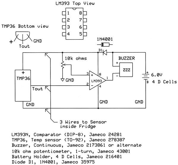
The three connections are power (pin 1), temperature-voltage output (pin 2), and ground (pin 3). The sensor provides a learning opportunity because you can use a simple voltmeter to measure the temperature in your refrigerator and experiment with ice water, hot tap water, and so on. Just solder three wires to the sensor and apply power. Use heat-shrink tubing to insulate the bare leads on the LM36 and the solder connections. A few dips into clear nail polish help with waterproofing.
The slope of the TMP36 output voltage amounts to 10 mV/°C, with a 500 mV offset. Thus at 1.5°C, the temperature of an "average refrigerator," output should read 615 mV, or 500 mV + 15 mV. At 100°C, you should measure 1.500 volts. Just remember to subtract the 0.500V offset if you calculate a temperature from the sensor's voltage output. Don't worry about the exact voltage: The sensor has a typical tolerance of ±1°C.
To turn on an alarm when temperature increases beyond a specific point, an analog comparator does the job. The LM393 offers a good example. You get two comparators in an 8-pin dual inline package (DIP) but use only one for the fridge monitor. The second comparator stays unconnected. The LM393 has two inputs, Vplus (pin 3) and Vminus (pin 2), and one output (pin 1). The IC takes power at pin 8 and connects to ground with pin 4. When Vplus > Vminus, the output becomes a logic-1. When Vplus < Vminus, the output switches to a logic 0, basically a connection to ground. This latter condition acts like a switch to ground and it lets the comparator control a small piezoelectric buzzer connected between the power supply and the comparator output. (Or you could use an LED as a visual indicator.)
To use the comparator, connect the Vminus input to the LM36 sensor output. Connect the Vplus input to a variable resistor--10K ohms will work well. This resistor lets you set the "trip" voltage between ground and the power supply voltage. Adjust the resistor to the point where the buzzer just turns on or just turns off. Then make a slight adjustment in the direction that turns the buzzer off. This change gives the comparator a reference voltage at the comparator's Vplus input. When the sensor voltage exceeds this "set point" voltage, the buzzer turns on.
PUI Audio and Mallory Sonalert manufacture loud piezoelectric buzzers. Choose one in your hearing range. AQll Electronics has a loud siren (ES-25) that operates from 6V and will alert everyone in your house to the open fridge door! You can create a circuit on a piece of solder breadboard. Try the SB300 Solderable PC Breadboard available via Amazon.
For power use four D dry cells. A diode in the circuit drops the voltage from 6 to about 5.3 volts. That's within the range of recommended voltages for the LM36 sensor.
Jon Titus
Herriman, UT
Is there any "technical" difference between tube amp distortion and solid-state amp distortion? I have heard tube amps described as “warm” sounding but I can’t find any info as to why. Isn’t “clipping” just “clipping” no matter the device that is performing that function?
#11165
Alison English
Tampa, FL
Please log in to post an answer.
Answers
The soft or “warm” sound of tubes relates to four properties.
- Rolled off frequency response of the amplifier related to the inductance of the output transformers.
- Slower transient response again due to the high inductance in the output transformers.
- Soft clipping for very large amplitude signals due to the transfer characteristics related to the amplifier tubes.
- Magnetic hysteresis in the transformer itself which alters the output signal of the tubes.
Transistor amplifiers have much higher slew rates, higher frequency response, and hard clipping when the large signals cause the output transistors to hit the rail voltage of the power supply.
Solid state amplifiers are directly coupled to the speaker load, have a very high damping factor due to the negative feedback, and therefore produce much more accurate output than a tube type, amp. This is the reason for the harsher sound which is really more accurate than the output from a tube amplifier.
If you compare the FFT (Fast Fourier Transform) frequency domain traces of the two types of amplifiers, the differences will become readily apparent. A solid state amp will have many more harmonic components than a tube amp. The direct coupling of the solid state amp to the speaker, also eliminates the hysteresis from the transformer core.
The lowest distortion figures will always be obtained from a solid state amp, in the less than .1% range. Tube amps, conversely are in the 1% to 5% range depending on their design.
Ron Hoffman
Solon, OH
Yes, there are technical differences. Both tubes and transistors are nonlinear devices, and the transfer curve for each is unique. The transfer curve defines how the output should respond to the input. Within a narrowly defined range of input values, the output values change in “mostly” linear fashion — in math terms we would say the function is monotonic. When your input values start to go beyond the linear operating region the output is no longer a simple (linear or monotonic) function of the input.
Every device, triode, pentode, JFET, MOSFET, BJT has a unique transfer curve. Imagine that the transfer curve for a triode is not a straight line, but more of a “lazy-S” shape — the middle section is pretty close to straight, but the top and bottom of the curve rolls over. As mentioned above this curve “maps” your input signal to the output signal; any given value of input is a point on the curve that defines the output. But when the signal is near the very top of the curve, the output signal change for a given change of input is diminished (like a demon turning down your volume knob). This results in a soft clipping effect if the top of the transfer curve is relatively smooth. Gentle excursions into nonlinear behavior in a triode tends to produce a nice mix of even and odd harmonics; and, if I recall correctly even harmonics lend warmth to the sound.
In the case of a BJT (bipolar junction transistor), the “lazy-S” curve looks more like a “Z” drawn backwards, where the extremes of the transfer curve don’t bend gently. Instead, they have sharp “corners” and tend toward a “flatter” transfer function at the extremes. When the input signal gets into this nonlinear region a large change of input signal results in almost no change of output signal, but can produce lots of harmonics — predominantly odd-harmonics.
The clipping is more aggressive at the extremes of signal input; almost an “all or nothing” affair. Contrast that to the tube clipping, which is more like “diminishing returns.” I have heard of an amplifier circuit that adds even-harmonic components of the signal. I haven’t built it, but the idea is that it would create a warmer sound.
Having said all that, clipping and harmonic content (warm versus cool) should not be thought of as synonymous. Clipping occurs at the extreme limits of signal input. Nonlinear transfer curves can create harmonics at any value of input signal. When you look in the mirror in the morning, you are seeing a “linear” reflection of yourself. At the carnival or fairground when you stand in front of curved mirrors that distort your reflection, you are seeing an exaggerated “nonlinear” reflection of yourself. While seeing such exaggerated nonlinearity is humorous, in the audio realm it would be intolerable to listen to... maybe.
Guitar effects pedals intentionally distort the signal, sometimes to an extreme that is almost unrecognizable — but, that’s an article for another day.
Doug Manchester
Rocklin, CA
The answer is simple, really. Tubes don’t so much clip, as go soft, rounding the peaks off the waveform. Solid state, however, works all the way up until it hits the head; at which point it cuts it off sharply. The resulting distortion can be either modeled as odd harmonics for solid state, or even harmonics for tube amps. And it’s all in how they are perceived by the ear; the softer clipping that tube amps do causes it to be more perceived as being not quite as loud, whereas the hard clip of solid state tends to be rougher sounding. And to conclude - if your system routinely clips, you need to Tim Allen (MORE POWER!) it.
Ralph Phillips
Bossier City, LA
In this case, all clipping isn't the same. A transistor circuit is fine up to the power supply voltage, where it mows the peaks off square and flat. This produces a harsh distortion similar to the fuzz pedal for a guitar. A tube circuit starts to round off the peaks before they actually run into the power supply voltage. The rounder peaks account for the "warmer" sound.
Chip Veres
Miami, FL
It's not about clipping. Tubes and FETs have greater inherent 2nd harmonic distortion which gives them the warm sound. Look up the books and articles by Douglas Self to truly understand why modern bipolar output amplifiers are very hard to beat for sonic clarity. Some of the new Class D amplifiers (TI, others) are quite amazingly clear, too. I still use FET input op amps (LF412) when I want some of that tube warmth. But when I need absolute clarity, modern bipolar devices (LM833 and newer) for crossovers, and bipolar output stages, are (in my opinion) best. Read what Self has to say.
Jim Lacenski
Bellevue, WA
It has to do with the type of distortion between the two architectures. Tubes tend to have more odd-order harmonic (3rd, 5th, etc.) distortion; solid-state amps are relatively distortion-free, and any distortion they have is generally with even-order harmonic (2nd, 4th, etc.) distortion usually generated by their feedback circuitry. With clever signal filtering schemes, solid-state amps can mimic the warmth, etc. of tube amplifiers, without the power-wasting (i.e., heat) that tube amps have.
Ken Simmons
Auburn, MI
Simple answer: To the first order, they are pretty similar, however, typically tube circuits are operating at a much higher voltage — a transistor circuit operating at lower voltage, will tend to have higher harmonic distortion than a tube operating at a higher voltage. If you use a high voltage transistor then you can get harmonic distortion from a transistor which is comparable to (or better than) a tube, but you usually have a higher noise floor.
Mark Sauerwald
Tacoma, WA
I come from a TV engineering background, so I know I am asking for a lot. This is a very preliminary step in a design process, so I know it may go nowhere.
What I want to do is simultaneously view a small object/area (~ 1/4”) from two angles that are 90 degrees apart. Imagine a straight pin stuck into a board. I want to have magnified views of that point from the front and one side at the same time. These views will be at an angle above the board — perhaps 20 to 30 degrees — but they will be 90 degrees apart as viewed from above.
One way that I can think of doing this would be to use two of those small video cameras that are widely available for under $50. I do not need color images; black and white would be just fine. Two monitors would be too much, so I need a way of combining the two unsynchronized video signals to be displayed on a single screen, side by side.
What I am looking for is a combination of a frame synchronizer and a special effects generator that can do a split screen in one or a set of chips. I would think that anything current would be digital in nature, but an analog circuit would also be acceptable. Does anyone know of such a chip or set of chips?
Relatively inexpensive video surveillance systems can display multiple images on a single monitor, so there must be something out there. Of course, price is an important consideration. I would like to keep the entire project to under $200.
The only other alternative I can think of is to use mirrors to combine the two images optically and use a single camera, but that also has a lot of complications and expenses.
#11164
Edward Alciatore
Beaumont, TX
Please log in to post an answer.
Answers
Why not just get an inexpensive 4 channel video surveillance box? Some can be bought without a hard disk, making them less costly.
Bert
Toronto
I sometimes forget to turn the headlights off on my car, so I wake up to a dead battery and a late start to work. I would like to build a DIY auto headlight on/off switch. Anyone have a schematic or design?
#11163
Daniel Lemann
Milwaukee, WI
Please log in to post an answer.
Answers
After a couple trips across town to jump start my wife’s car, I installed a relay to automatically turn the lights off when the ignition was turned off. All you need is one of the generic automotive 30A relays. If you can find the power wire to the headlamp switch, cut it in a convenient place and place the contacts of the relay in series with the headlamp switch. Then connect the relay coil between a switched 12V source (turns on/off with ignition) and ground. The lights will only work when the ignition is on.
If the power wire for the headlamp switch is inaccessible, then remove the headlight fuse, get a relay and an inline fuse of the same value as your headlamp fuse. Then connect the fuse to the hot side of your original fuse holder, the other side of the fuse to one of the relay contacts (usually 30) and the other relay contact (87) to the other side of your original fuse holder. The coil connections will be as above.
Allen Bradley
Greenville, SC
Auto-headlights is moderately difficult because of the length of the delays and the quiesient current. Probably best done with a microcontroller; Light level sensing is generally time based and then it stays on until the ignition is turned off. I don’t know what the times are. But take going under a bridge a mile long or so. I think it takes about 20 seconds for the lights to turn on, Never paid attention to the off threshold/time.
I can, however, offer you a simple design that I used in 1982 on my vehicle. In that particular vehicle, there was +12 available when the tail lights were on and ground via the driver’s door switch, when the driver’s door was opened. There was already an isolation diode there anyway, so I took advantage of it. I had an EASY way of “buzzer on if lights were on and driver’s door was open.” So (to +12 when parking lights on), a piezo buzzer and a diode to the driver’s door switch (ground when open, +12 when closed). I had to replace the buzzer a few times in 17 years. The high temperature kills them.
Now, one car has 1. Lights stay on until the driver’s door is opened (actually radio too) 2. A few different delays are possible for how long the lights stay on.
The other has 1. Lights turn off when the door is opened and car is off. Both have auto-on by daylight sense. In both of these cases, in order to turn-off the lights when the engine is on, you have to do something heroic.
Car #2 Turn-off car and open the door. Turn off the headlights. if they are on.
Car #1 Stop. Turn off car, engage parking brake. Turn on car which will turn off lights. If you want to start the engine with the lights off, the parking brake must be set. Turning them off is not so easy. Blinking the high beams is easy on car #2 (momentary and full on stalk switch). In car #1 it’s not possible. For auto-on; timed off, there are a lot of issues to deal with. Turning the lights off briefly is very useful if you confront a deer.
Ron Dozier
Wilmington, DE
You just need a 12 volt, single pole single throw relay. Wire the contacts in series with the headlight power wire and power the relay from the ignition switch accessory terminal. You may have to find it by trial and error among the wires coming out of the steering column, or a auto repair manual may tell you the color of the wire.
Russell Kincaid
Milford, NH
Typically, the easiest way to do this is to connect a diode, a suitable resistor and a sonalert from the headlight switched positive to the RUN position of the ignition switch. If the headlights are left on when the ignition switch is turned off, the sonalert will sound. The diode prevents the sonalert from sounding when the car is running and the headlights are off. The resistor scales the 12VDC to a lower voltage for the sonalert if necessary. This is much simpler then an automatic switch, and it consumes no power.
Dave Bassett
The Villages, FL
I have a GFI type breaker for my garage door that trips occasionally, making it so the door won’t open with the remote. I’d like to know how to test the GFI to see if it has gotten weak or failed in some manner.
What’s the best method to test it?
#11162
Henry Doran
Phoenix, AZ
Please log in to post an answer.
Answers
I have to ask myself why anyone would put a GFI on the garage door opening circuit/electronics? I see no need for such a thing.
The reason we have GFI protected outlets is because someone could unintentionally become a ground path for the AC current. This could be deadly.
With a garage door circuit, no one should be playing with the circuit unless the electricity to the unit is off. It is a servicing issue NOT a use issue.
In other words, if the circuit is being used as intended, then there is no way you will inadvertently become a grounding path for the circuit. The circuit is protected in a housing and not available, as is an AC outlet, for you to come in contact with.
Disclaimer: This is an opinion of the sender only, not advice as to what you should do.
Phil Karras, KE3FL
Mount Airy, MD
You can buy them. You can make them. What is the normal trip level, you’d have to look up. A resistor (suggest metal oxide) from ground to hot, at about 6 mA should trip the GFCI. e.g. R<=120/0.006 The problem is more complex when you look here: www.csemag.com/single-article/ul-s-new-gfci-classes/89c8746cdc4a7fd8a3cb93f1d51ba57a.html I actually suspect that you may have an AFCI/GFCI combination and it’s tripping on an arc fault because of the motor. If that’s the case, I would consider an RFI filter (possibly medical grade which has a lower leakage) and appropriately sized ZNR’s. There have been reports of just plain flakey GFCI’s. So contact the manufacturer too.
Ron Dozier
Wilmington, DE
Working with live power lines can be dangerous. I purchased a GFCI tester from Home Depot similar to this one: www.homedepot.com/p/Gardner-Bender-120-VAC-GFCI-Outlet-Tester-Case-of-5-GFI-3501/202867890. To verify that the GFCI outlet can deliver higher currents, plug in a hair dryer or room heater. Make sure you don't overload your circuit. The trip level for a UL 943 Class A GFCI is 4 to 6 mA, or about 24K ohms from hot to safety. I don't recommend building your own circuit. Buy a device that is already built for this purpose.
Dennis Page
Beverly Hills, MI
As indicated in http://hyperphysics.phy-astr.gsu.edu/hbase/electric/gfi.html , a GFI is supposed to trip if there is 5 mA of difference in current flow between the hot and neutral (return) wires in the protected circuit. The "test" button puts a resistor between the hot and ground wires. You could put a larger value resistor between the hot and ground to see if the GFI does not trip with some smaller current. A 56K resistor, for instance would provide about 2.1 mA. If that trips the GFI, then the GFI may be too sensitive. It is more likely that there is an intermittent short to ground in the door opener, or that the door opener is too close to the current limit of the GFI (which also acts as a circuit breaker, usually 15 or 20A).
Phil Martel
Salem, NH
Your best bet is to replace the breaker — don’t waste the time, etc. trying to “test”it.
Ken Simmons
Auburn, MI
Many hardware or big box stores carry testers for receptacle testing, they have three lights to indicate correct wiring. Some of these have a test button to check operation of the of GFI devices.
Dave Bassett
The Villages, FL
After the recent “forced” update to Windows 10, I am so frustrated with big computers and big software companies. I’m thinking of downsizing to the smallest, simplest computer I can manage.
Has anyone successfully replaced a desktop PC with a Raspberry Pi?
#11161
David Grear
Temple Hills, MD
Please log in to post an answer.
Answers
It is possible to use a Raspberry Pi as a Linux desktop computer, although you’ll find that it’s quite slow for many things and the selection of ready to go software is somewhat limited.
You can however install Linux on your current PC in place of Windows and the result will be a much more powerful and versatile machine that is otherwise very similar to the Raspberry Pi in function. The range of Linux distros can be overwhelming and opinions on which is best are nearly as numerous. If you are relatively new to Linux and want something that just works, I would suggest trying either Mint or Ubuntu as both strive to be beginner friendly and come configured with a look and feel that will be familiar coming from Windows.
If you are feeling a bit more adventurous then Debian is one of my own favorites. If you want to test drive Linux before you make a commitment, look for what is known as a “Live CD” which is a CD or DVD you can boot the PC from without making any changes to the existing operating system.
James Sweet
via email
I attempted to use a Pi for a desktop, and it works, sort of. It was OK for web surfing but had some trouble with videos and other complex pages. Almost everything had some limitation. It worked great as a internet radio streaming device though, and that is where it lives now.
You also have to have a monitor with a HDMI or composite video (with an adapter with Pi 3) input, and by the time you buy all the pieces you need to make it work, you have spent a few bob.
Linux is the solution. Linux Mint KDE is my current favorite. If your current computer will run Win 10, it will have no problem with Linux. I have been basically Windows free for the last 10 years and it has progressively gotten better and better. You can even dual boot it with Windows if desired to run those few pesky programs that refuse to run in Linux.
Allen Bradley
Greenville, SC
As much as I am liking my new Raspberry Pi 3, I am not ready to ditch my (Windows) computers and go all Pi. The OS seems very skinny on error handling. One ends up in the command line all too quickly. While the included LibreOffice performs OK, I feel a much better choice is Ubuntu if making the switch from Windows. Or consider a refurbished Windows 7 machine, which are plentiful. The Pi does quite fine for web browsing, but when it hiccups things get obtuse very fast.
Jim Lacenski
Bellevue, WA
I know some people who use Pis as their main computer. However, be aware that they are designed to run LINUX only (specifically, the “Raspberry Pi” version supplied), and they are not designed for heavy-duty use (i.e., games, audio/video processing, etc.). If all you need is a basic machine for Open Office and light web use (i.e., check e-mail), then a Pi could be what you want. Do a web search regarding Raspberry Pi accessories (there are many!) and applications to use to further see if a Pi-based machine is for you.
Ken Simmons
Auburn, MI
I’m refurbishing a vintage video arcade game. There is a transformer between the video monitor and the mains power but it measures as open. From the schematic, it seems to be a simple 115 VAC 1:1 isolation transformer. Is an isolation transformer necessary when the entire cabinet is wood, or is it overkill? It would seem that the wood cabinet would be enough protection to prevent contact by a user with the AC.
#10165
Thomas Greer
Augusta, GA
Please log in to post an answer.
Answers
No! This is wrong!! The isolation transformer powering the monitor in an arcade game is there because the older monitors use a "hot chassis" design meaning that they contain no internal isolation from the AC line. The ground that the signal input is referenced to is not ground at all without an isolation transformer! Connecting a monitor to the logic board in the game without isolation is going to result in a flash and bang that usually causes serious destruction to both the monitor and the logic board. It is not there to protect the player from electric shock as the published reply states. All exposed metal parts must be bonded to the ground wire in the power cord for that.
Arcade monitor isolation transformers are readily available and inexpensive. I hope this answer reaches the person who originally asked before they take the advice that was printed. Note that some newer monitors do have built in isolation but unless this is known with certainty *do not* attempt to bypass the transformer.
James Sweet
via email
I'm worried that the monitor discharging advice given here could potentially kill someone. While the alligator clip/long screwdriver method is sound, touching the corners of the CRT is not. To discharge the monitor the screwdriver has to be inserted under the anode cap. Just touching the CRT or frame will not discharge the monitor, and could result in 20,000-30,000V being discharged through the tech. CRTs contain very high voltages. Please make sure you know what you are doing before attempting to service one.
Concerned Tech
I read the published answer to this in N&V, and the arcade preservationist in me cringed a bit. If the cabinet had an isolation transformer, in the bottom, you definitely want to run it with one. The transformer is actually there for the monitor, not the game PCB. The older CRT monitors used in arcade games don't have an internal isolation transformer on the chassis, unlike newer CRTs with an internal switching power supply that do. Running without an isolation transformer will most likely result in a dead monitor. Most arcade monitors run without an isolation transformer will end up blowing their Horizontal Output Transistor (HOT).
William McCarroll
Raleigh, NC
The transformer, if it really is a 1:1 isolation transformer, is probably for your protection not the user’s protection. Second it may also be to insure that it doesn’t matter how the plug (I’m assuming it is non-polarized) is plugged into the wall.
On the other hand if this is an older unit with a picture tube the transformer might be the horizontal flyback transformer that generates anything from 10,000 to 30,000 volts to be placed onto the picture tube. However, a flyback does not look like an isolation transformer, so I have to assume it is not one of those and that you know the difference.
Thus we’re back to my first two possibilities, it is for service safety and using a non-polarized plug - again service safety. Just be sure to unplug the power cord, then discharge the picture tube, wait about 15 - 20 seconds and discharge the picture tube again, repeat until no spark is generated. The old standard way to do this is to use an alligator jumper from ground to a big/long screwdriver with an insulated handle & bring it close to some part of the picture tube, then do it again to a different part of the tube. The picture tube has four corners so I would go round & round till no more spark jumped.
Phil Karras, KE3FL
Mount Airy, MD
The isolation transformer is for protecting the MAIN METAL PARTS of the arcade machine from electric shock - specifically the coin-handling mechanism. If you’re not going to use the coin machinery (i.e., replace it with a switch or similar), then you could probably get away with not using the line isolation transformer. HOWEVER, consider integrating EMI/RFI/surge protection on the AC power input to help the machine live a little bit longer.
Ken Simmons
Auburn
I have an Apple iPod and lost the little USB charge brick. I have a USB charger that works with my cell phone but it won’t charge the iPod. Is there something “special” about the Apple iPod charger and if so, can I modify a “regular” charger to work with both?
#10164
Brandon Barajas
Clarion, PA
Please log in to post an answer.
Answers
Yes, the iPod requires a higher current to charge and so a simple 200 mA 5V USB brick won’t work. The higher bricks are usually modified to indicate to the plugged in device that higher current is available.
You can actually build the circuit that gives the right voltage level on the data pins to indicate this capability, but an easier “fix” is to simply modify a USB extension cord by opening it up & shorting the two data lines the iPod “sees” together. I’ve made a number of these & use them for a number of reasons.
- I can plug it into ANY computer & charge the iPod without it trying to sync.
- I can use non-standard iPod chargers to charge my iPod, as long as they are 500 mA or above.
You can also look up the difference between a low and higher powered USB charger on the Internet to see the specifications and schematic. Or at least when I did that years ago I found what I was looking for & found my “fix” was much easier to implement.
Phil Karras, KE3FL
Mount Airy, MD
In order for the IPOD to charge using any USB charger you need to use a small adapter.
Apparently Apple chargers have a resistor between the 2 data pins inside the charger. I had a similar issue when trying to use a non Motorola or car charger with the Razor V3M phone. A small adapter does the trick and makes the device think a genuine charger is connected.
You can get one here:
www.boxwave.com/apple-ipod-nano-3-travel-chargers/apple-ipod-nano-3-ipod-charging-adapter/bwpdd/fpz-gcgz/
They run about $8 or so.
Bruce Bubello
Apex, NC
There is no reason for it not to charge unless the iPod charging port is damaged. Both a phone and iPod should have similar charging requirements.
Anonomous
via internet
In order for the iPod to charge using any USB charger you need to use a small adapter.
Apparently Apple chargers have a resistor between the 2 data pins inside the charger. I had a similar issue when trying to use a non Motorola or car charger with the Razor V3M phone. A small adapter does the trick and makes the device think a genuine charger is connected.
You can get one here: www.boxwave.com/apple-ipod-nano-3-travel-chargers/apple-ipod-nano-3-ipod-charging-adapter/bwpdd/fpz-gcgz/
They run about $8 or so.
Bruce Bubello
Apex, NC
iPods require voltages on the data pins of the device in order to charge. If your charger has just the positive and negative pins connected to the plug, your iPod won’t charge. This is probably the case. Search the net for USB charger circuits.
The modification will require four resistors wired from ground (negative) to positive as voltage dividers. One pair for Data + and the other pair for Data -. According to the circuit diagram I found you will need two 27K resistors, a 22K, and a 39K. The two 27K resistors are wired to ground (negative) pin 4 on the charger plug. The 22K and 39K are wired to the positive pin 1 on the charger plug. The junction of the 27K and 39K divider is wired to pin 2 (Data -) on the charger plug. The junction of the 27K and 22K divider is wired to pin 3 (Data+) on the charger plug.
Also, for an iPod you should have a charger capable of at least 2 amps output. The wimpy 1 amp chargers will take a much longer time to charge apple devices like an iPod. To be sure which pins are which, just do a search for USB pinouts.
Richard Washburn
Naguabo, PR
I’d like to dive into doing surface-mount projects. I’ve heard of people using a regular toaster oven for soldering. Will an off-the-shelf oven work or is a special temperature controller required for a satisfactory result? Or, would I be better off just soldering by hand to start?
#10163
Michael Yon
Farmingdale, NY
Please log in to post an answer.
Answers
There are circuits to control a toaster oven to make a reflow oven, but I get decent results using a normal toaster oven and the following procedure:
- Mark the top of the toaster oven with a sharpie that it is never to be used for food.
- Use standard Tin-Lead solder paste, with a low melting point.
- Get a stencil to help screen the paste on your board - OSH stencils work fine for most hobbyist work (low volume).
- Once you have placed the components, put your board in the toaster oven, and turn it on to bake at a low temp (~250) and leave for 5-10 mins to bake out any moisture.
- Turn the toaster up to broil, and keep an eye on the board - you will be able to see when the solder melts and begins to flow - I usually wait 20-30 seconds after I see the solder begining to flow, then turn off the toaster oven.
- Open the door and allow the board to cool for 5-10 mins before moving it, then take it out of the oven and let if finish cooling on your bench.
Mark Sauerwald
Tacoma, WA
I am this very moment seeking the same solution you are for a variety of surface-mount (SMD) projects. I also have a cheap unused toaster oven just waiting to heat things up!
Two temperature control approaches are readily available, with one being more complicated with PIC processor and other components. I am “Old School” and not yet experienced with programming these, but I located a nifty Nuts & Volts article about a toaster oven controller. This article appeared in NV’s June 2008 issue, authored by Kit Ryan, entitled “Oven Flow 1.0.” I just printed the article out after hunting through my .pdf collection of NV. You should give this a read because K. Ryan covers the essentials of reflow soldering SMD devices. Important for success is knowing and maintaining the proper Time vs. Temperature profile. The temp ramps up, levels off and then ramps down all under processor control. Kit also refers to SparkFun’s Electronics Reflow Toaster Controller for toaster ovens!! Another reference is to Kester’s SMD soldering time/temp profile (kester.com) and I plan to read it: you should too.
The 2nd least complicated method is analog and manual. Should you mount a readily available barbeque thermometer inside your toaster, you’ll be able raise/lower inside heat and time the temperature transitions with a watch. I understand this not-very-fancy-at-all method and notice my grill’s temp gauge reads up to 700 degrees F. That’s more than enough range to see SMD solder paste melt. My grill’s gauge is a replacement I bought in the BBQ section of a local big box store and is not expensive. Now all I need is patience and a working clock!
BGoodWill
Rahway, NJ
Toaster ovens are used for surface mount soldering. Usually there is a temperature profile that is used. Sparkfun Electronics made a kit that you could use to control a toaster oven but they don’t sell it anymore. You could probably find the temperature profile on the net and do it manually. You can also use a heat gun to solder surface mount devices by putting solder paste/solder flux on the pads and then heating up the board with the heat gun. I have found this to not be reliable, especially if there are other parts already soldered on the board.
Another way to do it is manually. If the PCB was tinned when it was produced, it is possible to tack down a few key pins on the board and then solder the rest. This requires a very fine tipped soldering iron, very small diameter solder, and a lot of patience, but it has worked for me.
A few other notes. Getting the solder paste/flux onto the board without bridging adjacent pins is tricky. Often times, a stencil mask can be made when the board is produced. They make it easier to get the solder paste /flux down accurately. However, they come in various quality levels with the good ones being higher priced.
Anonomous
via internet
For one-sided boards, electric skillets are known to work. You also need a pair of tongs to get the board in and out quickly. If you simply turn the skillet on and wait for it to heat, the flux will burn off before the solder melts. Unfortunately, I presently have a workbench full of boards with components on both sides. For me, it's back to the soldering iron.
Chip Veres
Miami, FL
I found a partially assembled kit labeled “Fish Caller.” Does anyone have a schematic for one that I could use to finish it? Also, what’s the theory behind how it works ... or does it?
#10162
Carl Kaminski
La Porte, IN
Please log in to post an answer.
Answers
Theory: It makes a ticking sound that sounds like a dying fish which attracts other fish.
You might try: https://www.electronickits.com/electronic-fish-caller-plan/ On the other hand if all it does is tick, you now know what the circuit is supposed to do and you might be able to complete it with just that much information. The above link sells plans to build such a thing. There are others selling kits as well. I simply did a web search to find the above.
Phil Karras, KE3FL
Mount Airy, MD
I built one years ago. It was designed to produce a high frequency noise that supposedly attracted fish. Maybe my fish were hard of hearing but it never worked in my field trials. I have never seen them promoted in any fishing supply catalogs either.
M Herman
LaQuinta, CA
Seriously, you can find all the circuits you want by Googling "Fish Caller Circuit" and looking at the images. Less than seriously, it emits Fishy Language for "Neener neener neener! You can't catch me!"
Chip Veres
Miami, FL