I need a simple circuit to sequentially flash three separate strings of 10 LED lights. Flashing two strings is easy; three is tougher.
#2173
Michael Herman
La Quinta, CA
Please log in to post an answer.
I have been using a Sony ICF-9740 AM/FM table radio on my nightstand since 1974. Recently, there is increasing interference on the AM band. It’s not AC “buzz” or “hum” that one would expect from old power supply filter caps; it's more of a high frequency whine — my guess is around 6-8kcs, and it's consistent even when the volume is turned all the way down. I could replace this unit but I would really rather fix it. Any pointers on finding the source of the noise or theories on what might be causing it?
#2172
Radio Whine
Houston, TX
Please log in to post an answer.
Answers
I wonder if Mr. Casas (or a neighbor sharing the same utility transformer) has recently installed a new central air conditioning system. Many of these systems employ a condenser (the outside unit) having a variable-speed fan. The fan is a three-phase motor powered by rectifying the AC mains power, then using an inverter circuit to convert the DC bus voltage into a three-phase AC voltage. The fan provides tachometer feedback so that the inverter provides three-phase power at the frequency needed to maintain fan speed to the degree desired by the control circuitry.
The inverter operates using pulse-width modulation techniques. A chopper frequency in the range cited — six to eight kilohertz — is not unreasonable, being sufficiently high to be significantly greater than mains frequency yet low enough to avoid the magnetics and copper losses that would otherwise occur if the frequency were higher.
The problem is that some of this chopper operation may be leaking back into the AC mains supply. The DC power filter capacitor(s) in Mr. Casas's radio do an acceptable job of smoothing the AC mains-frequency ripple; for cost reasons, however, there is no reason why the manufacturer would have chosen capacitors having equivalent series resistance (ESR) sufficiently low to filter kilohertz-range noise.
My suspicion is that Mr. Casas's radio is receiving power-line-conducted chopper noise. Since it comes via the power system, it will be presented to the radio's audio amplifier regardless of the volume control setting.
Peter A. Goodwin
Rockport, MA
I have found that a light dimmer can cause buzzing on the AM radio band. If you tune to a strong station that will usually drown the buzzing.
Daniel Robert Zielinski
Port Saint Lucie, FL
This sounds like interference that is coming from some other device that you probably placed nearby the radio, like a cell phone charger or dock. Sometimes, LED lamps can create nasty interference. So can flat screen TV sets and computer monitors. (Even when they are OFF!) Try unplugging various devices and eventually, you should be able to find the culprit. The other option is to use a transistor radio, and walk around to see where the noise gets worse. This is how I found interference in the past.
William Barnett
West Haven, CT
I have an electro-mechanical gambling machine — Galloping Dominoes — from the company Auto Bell, and would greatly appreciate if someone could direct me to where I could find a schematic. It has a motor that turns four large switch cams and three smaller cams, and has numerous multi-pole relays all interconnected. Thanks!
#2171
Randy Grunwell
Suwanee, GA
Please log in to post an answer.
When designing circuits, is there a rule of thumb for picking voltages and tolerances of components? For example, if my power source is 12 volts, is an electrolytic capacitor with a 24V rating “better” than one with a 16V rating? What do good designers use as a margin?
#1174
Enrico Gutiérrez
Panama City, FL
Please log in to post an answer.
Answers
I used to design circuits for military applications and in that environment, a voltage rating double the expected maximum was considered adequate. In an automotive application, the spikes from the starter can exceed 60 volts, so you need to keep that in mind and provide isolation.
Ripple current is another capacitor parameter that needs to be addressed. It turns out that ripple current rating increases with voltage rating, so you might use an electrolytic cap with 10 times the needed voltage rating just to get the ripple current rating.
In general, the MTBF (mean time between failures) is calculated based on the stress on the component. A component (resistor, transistor, transformer, etc.) that is rated 70 degrees C but is running at 150 degrees C will have a short life, but if it’s running at 30 degrees C the life will be normally long.
Russ Kincaid
Milford, NH
I have a newly restored 1971 Honda CB350 motorcycle that I ride for fun on the weekends. One problem is forgetting to turn off the turn indicators. I have found a kit that “beeps” every time the indicator lights up, but it's very annoying as I sit at a light. I would like a circuit that would alert me only if the turn indicator stays on for more than two minutes. Schematic would be welcome!
#1173
Leland Collins
Gulfport, MS
Please log in to post an answer.
Answers
I remembered that I had designed and built a gadget that may be the answer. A hand-drawn page is attached, a bit crude but it says it all.
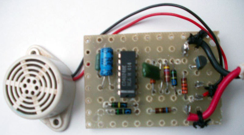
The piezo buzzer will sound after 64 blinks. Pulsing 12V will charge C1 via D2 + R4 (soften the charge spike). C1 supplies power to the seven-stage ripple counter. It holds enough charge for about three seconds. Pulses are fed to the counter input via D1 and R1. C2 will prevent spikes; R2 will discharge C2; and D2 will prevent input from going higher than Vdd + 0.7V. Output Q7 will go high after 64 pulses. R3 will limit base current to about 0.35 ma – enough to drive TR1 into saturation, but also stretching the discharge time of C1 to about three seconds.
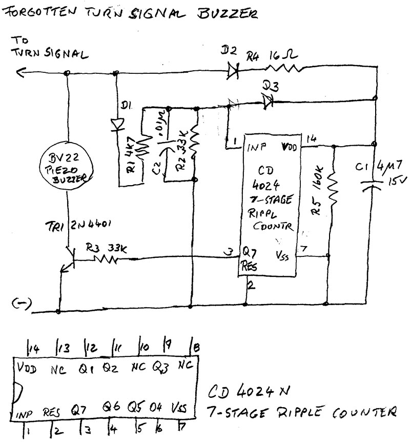
Note that 64 counts is about one minute. If not cancelled, the buzzer will sound for 64 blinks. The next 64 stay silent. When the turn signal is cancelled and left off for four seconds, the count will begin again.
Christian Bock
via email
Sounds like a job for an Arduino Pro Mini and a few discrete parts.
First you need to convert the on-off 12V turn-signal levels from the lamps or LEDs to 5V logic levels. You can find level-shift circuits via a Google search. Then you’ll have two sets of pulses, one from the left signal and one from the right signal. Run the 5V logic signals to two inputs on the Arduino Pro Mini.
Second you need a control program that determines what to do with these pulses and when to turn on an indicator (visual or audible). When the software detects a pulse on either input it starts two timers, Timer1 for 2 minutes and another (Timer 2) for about 1.5 times the length of a turn-signal on-off period (1.5 times the flash duty cycle). Each incoming pulse restarts Timer2. So as long as the Arduino Pro Mini receives turn-signal pulses, Timer2 continues to run. If at the end of the 2-minute period Timer2 is still running, the indicator turns on. The indicator turns off as soon as Timer2 stops running. That indicates no more pulses from the turn signal.
As an alternate, an Arduino Pro Mini could simply count the number of pulses that occur for your vehicle in a 2-minute period and when the count equals that number, it turns the indicator on. You might include a “kill” switch for the indicator in case you need to keep the emergency flasher on for more than 2 minutes. For more information about the Arduino Pro Mini, visit: https://www.sparkfun.com/products/11113.
Jon Titus
Herriman, UT
I found a bargain at a local thrift store and now have a 1959 Marklin HO Scale train, cars, and track. The set didn’t come with a transformer, so I thought it would be a fun project to build from scratch. Does anyone have a schematic or suggestion for a DIY train transformer they can share?
#1172
Alfred Thompson
Kingsport, TN
Please log in to post an answer.
Answers
I have been collecting Marklin trains since 1962. I believe, what you are looking for is the 16-20VAC transformer Marklin used to require. The basic power pack was a variable voltave, 0-16VAC approximately, transformer. It had a lever to rotate which increased/decreased the voltage output.
To reverse the engine, the hadle was pushed down momentarily, which would send 20VAC to the engine, which toggled a latching relay in the engine to reverse the ‘brushed, AC motor.’ Were I, and I might in the future, to design a solid state replacement, I would select a PIC24F or PIC33F series processor and have it geneterate a PWM sign wave. There are app notes at the Microchip website specifically regarding the digital generation of sine waves. Then you can vary the frequency for speed control, rather than the voltage, which would give much better low speed response for the engine.
Mark Lampkin
Grand Rapids, MI
Boy are you lucky!!! I started collecting Marklin HO scale back in 1962, so a 1959 vintage should be fabulous.
The old equipment had AC motors in them, and the original transformers ran 16VAC to 20VAC. In other words, they were variacs which controlled the speed by changing the voltage to the tracks. This did pretty well, except at the very lowest speeds.
So, there are a number of ways to control the locomotive. The easiest would be to use a transformer output through a potentiometer, driving a 30 or 40 watt amplifier, (direct coupled). This output would directly couple to the track. The center spikes are the Hot, with the rails being the neutral.
A more complicated, (but fun way depending on your skill level), would be to use a PIC microprocessor to PWM a sine wave to directly drive the center rail of the track. Then you would have the most control.
Mark Lampkin
Grand Rapids, MI
I’ve used the Arduino IDE with a genuine Arduino Uno board for experiments for a few months without trouble. Recently, I wanted to permanently put an Uno in a desktop project, so I purchased some budget Arduino Uno compatible boards. The budget boards seem fine, but the Arduino IDE doesn’t recognize any of them. When connected, the boards show up as an “Unknown Device.” I am using Windows 7 32-bit. Does anyone have any pointers on how to make this board work?
#1171
Michael Allison
Camden, NJ
Please log in to post an answer.
Answers
This is a MINOR manufacturing defect, easily repaired! Turn the unit over, so the USB connector is on the bottom, and facing left. That "large" IC on the left is the USB controller. Solder pins 25 and 26 together, and your problem will be solved. One of those pins is ground. The other is a "test" pin that is SUPPOSED TO BE grounded, but isn't. Once grounded, the chip works correctly. I did this with a board I bought from MPJA, and it solved my problem instantly.
William Barnett
West Haven, CT
Some of the cheaper Uno and Nano board spinoffs (among other off shore versions) use the CH340G series USB serial interface chip rather than the FTDI USB chip. All that is necessary is to download the CH341 driver and install it in your Windows/Mac system. You can get the driver from Driverzone.com or Google search “ch341ser.zip”. Just make sure your comm port settings in the software match the USB driver in Windows. You can leave both drivers in Windows without uninstalling the other.
Rick Choy
Winchester, VA
On the bottom of the Nano board, are a few chips. One of them is much larger than the rest. That is the USB chip. You need to create a solder bridge between pins 25 and 26. One of those pins is GROUND and the other is a manufacturer’s TEST input... which they left floating. It needs to be grounded. Once you solder those pins together, your Nano will work. I’ve done this fix twice, now, and it solved my issues 100%.
William Barnett
West Haven, CT
I want to start experimenting with Software Defined Radio (SDR) There seems to be a fair amount of info, but I’m still not sure where to start. What are the minimum requirements to get started on a small budget that the wife will live with? Is there a best “starter kit?”
#12164
Amaranto Melgar
Wetmore, KS
Please log in to post an answer.
Answers
I use SDRSharp software with a DVB-T dongle with a Realtek RTL2832u control chip. These dongles are quite reasonable, and some are specially designed for SDR.
Bert
Toronto
My Raspberry Pi Model III uses a microSD card. The cards are available in different “speeds.” Is there any significance to how “fast” a card I get?
#12163
Rick Holtz
Grand Rapids, MI
Please log in to post an answer.
Answers
The answer isn’t really clear cut.
Class-10 SD cards are rated on the basis of streaming a single file to a clean (recently formatted) card. Essentially, what would happen with a video camera.
Class-2/4/6 SD cards are rated on multiple small files written to a fragmented card. Still image cameras where one has erased a few images.
One would hope that a Class-10 used for multiple small files would not be slower than a Class-6 card, but this is not always the case. Especially when used with a journaling file system — the ratings are based on FAT — where for single file writes one basically has the data file, and the File Allocation Table; journaling file systems, especially for something like EXT3 or EXT4 (common for Linux OS), will have things like the data file, inodes, journals, and bitmaps.
Flash memory needs to be erased to all “1” before it can be written — writes can only convert a “1” to a “0” but not the other way around. Erasure is done in large chunks. When doing small writes, the card allocates a cleaned chunk, then if needed, copies previously written data to that chunk before adding the new data.
Higher quality cards have the ability to “hold” multiple allocations “open” at the same time. These cards will function better on a journaling file system then a card that only holds two open allocations a time (which is all the Class-10 streaming model requires). Everytime a “2 allocation” card changes files, it has to close/flush any data changes to the card, then prepare a new “allocation” if changes are expected for the next file to be opened.
For FAT file systems, that means just closing the data chunk and opening another. For EXT3, that could mean closing a data chunk, opening an inode chunk and updating it, then closing it to open the next file chunk. Cards supporting 6 open allocations can minimize the number of times they have to perform the flush/close operation. They can flush a data chunk while still holding the inode/bitmap chunks active.
This may not be a concern if the device (RPI, Beaglebone Black) is used in an embedded mode, where the only data being written is a log file from some running application. But if the device is being used as an interactive computer, where one is compiling files, building applications, etc., a high end Class 6 card may be better suited than a low end Class 10, even if Class 10 implies nearly twice the transfer rate of Class 6. The RPI “NOOBS” OS starts out on a FAT system (it allows one to use native Windows to create a new card), but I believe the first step it performs is to repartition the card with an EXT3 file system, and copy the running OS into that partition. The Beaglebone Black OS images are currently EXT3 — and need special tools to create a card image.
Dennis Bieber
Kentwood, MI
Does anyone have a simple circuit that will allow me to mix my iPod audio out with my computer’s audio to play through the same speakers? I want to avoid un-plugging/re-plugging just to hear some music.
#12162
Jonnie Vanalstyne
Manchester, NH
Please log in to post an answer.
Answers
I was disappointed in the answer that missed the obvious. The question asked about mixing the audio, not switching it.
Most powered computer or pod speakers have more gain than necessary and could make due with the loss of a passive mixer. The signals from earphone outputs can be combined by using a series resistor on each before combining them in a small junction box. Use the resistors like wires between the jacks forming a "Y" connector. To each source, the other device looks like ground, so the two resistors form a 50% or 3 dB divider. The series resistance forms another divider with the input impedance of the speaker/amp, so it should be as small as safety permits. I frequently see a couple hundred ohms of resistance on headphone outputs just to limit the power to small headphones, so my guess is that something around 2K would be reasonable, but 5K would give extra isolation if you still have enough signal.
The idle device is not a perfect ground and could introduce some distortion, so better isolation matters if you are using Hi-Fi speakers (but we're talking MP3's from a pod). Use 5% or better values to maintain channel balance. You may want to check the outputs for DC leakage, which would suggest using a blocking capacitor (10-20 MFD). Microphone inputs on computers often provide a positive polarizing voltage for electret microphones, and some jacks are multi-purpose and electrically switched by sensing software. If the computer misidentifies the connected device, you probably don't want that voltage fed back to the pod or phone.
Dennis Green
Farmington Hills, MI
I use a simple DPDT toggle switch for something like this. I switch my computer output between speaker and headphones without wearing out the headphone jack.
In your case, the audio to the speaker would be switched between the iPod or the computer. The speakers must be amplified, and the computer’s output volume adjusted down to be close to the level coming out of the iPod headphone jack. You can mount the jack and switch on the speaker.
Bert
Toronto