I am building a mid-size Tesla coil. I want to study the frequencies produced and map the EM field potentials produced by my coil. Considering the high voltages and frequencies involved, typical RF measuring gear will not work. Does anyone have suggestions or links to help me build the device I need to do my experments?
#5171
Ron Sndric
via email
Please log in to post an answer.
Answers
For voltage, use a bunch of NE2 neon bulbs wired in series on a long wood stick. Each lamp lit stands for about 100 volts. For frequency, the coil probably operates at or below the broadcast band. If you can't hear it on a standard AM radio, buy or borrow a set with the long-wave band. None of this is lab-quality but I assume you want cheap and easy.
Chip Veres
Miami, FL
My daughter is in 4H and has a calf we are raising in a shed behind the house. Recently, the bulb burned out on the heat lamp we leave on to keep the cow warm. Is there a simple circuit I could use to remotely monitor the temperature and alert me if it drops below a set point? I know there are remote temperature gauges but I need one with an alert or a way to hack one to add an alert. Any ideas welcome.
#4173
Robert Lowery
Florence, SD
Please log in to post an answer.
Answers
Simplest is a standard (cheapest bimetallic) house thermostat, a battery, and a simple DC bell! You don’t have to drill any holes or screw anything up, and the wire can be taken through a window into the house. I’m sure you could also rig up something like an arduino with hats and bluetooth or Wi-Fi with phone messaging, but unless you want to do extensive datalogging, I can’t see the point...
But that’s often beside the point in hobbyist systems.
Sally Jelfs
Brackley/Northants
Sounds like a job for the Raspberry Pi 3 computer connected to a DS18B20 temperature sensor with Cayenne software installed on both the Raspberry Pi and mobile phone. Cayenne is a software platform from MyDevices that acts as a gateway to the Internet of Things (IoT), the service is free. You can view temperature data from your mobile phone, or configure Cayenne to send a text message alert when the temperature drops below a set threshold. The Raspberry Pi can be connected to your home network using Wi-Fi or wired connection.
Norman Ma
Calgary, Alberta
I need a circuit to generate 20 Hz 90 VAC to ring a POTS telephone on a theater stage. That’s Plain Old Telephone System vs. Pretty Advanced New Stuff (PANS) for the younger readers. If I could locate an old crank ring generator, it would work but would not be as convenient.
#4172
Dale Carlsen
Woodbridge, VA
Please log in to post an answer.
Answers
POTS ring generator modules are readily available prebuilt. The Tele-Q 70-9100 at www.musson.com is a self contained ring generator with simple pushbutton operation. Viking Electronics model DLE-200B www.vikingproductstore.com is a two way phone line simulator that will ring one phone when the other is picked up and provides loop current to power the phones.
For theatrical use this will ring the phone on stage but the ability to also talk on the phones may help the person on the phone have a more realistic sounding phone conversation.
Erik von Seggern
via email
I found this at: www.electronicspoint.com/threads/generating-a-20hz-90v-signal-phone-ringer.61314/ Seems like it would work fine for stage use.
I had an old Post Office local system ring generator that did the job very simply. It had a transformer with a split winding on one side, and a single winding on the other. The split windings were linked in series by a 2uF paper capacitor, and a single diode (IN4007 style) was in series with one of the outside terminals. The diode half wave rectified the mains going in, providing the transformer with half mains frequency pulses (25Hz in the UK). The cap between the windings provided rough tuning, which took the waveform back to something approximating a sine wave. Out of the other side of the transformer came a reasonable sine wave at about 80V p-p.
I guess that the same thing could be reproduced now using a split primary power transformer, with a secondary of say 40 - 0 - 40. The value of the cap could be played with a bit for best wave shaping to suit the tranny. I doubt that you would notice the frequency being 30Hz US or 25Hz UK. Arfa Daily, Oct 13, 2005
Andrew Gutierrez
Tehachapi, CA
It's called a ringdown circuit. Here's one assembled that would work, but if you search using that term, you should find something. www.sandman.com/simulator.html
Richard Allen
Perry, MI
eBay has a Black Magic Ringing Generator for $26. A pushbutton can be used to intermittently connect four “D” cells to the input of the Generator and it will ring the phone. Be sure to hook the battery to the Generator with the correct polarity shown on the label. Connect the output of the Generator to the phone’s red and green wires, but you must also put a 330 ohm resistor in series with one of the output wires to the phone.
To be realistic, the phone should be made to ring for 2 seconds, off for 4 seconds, on for 2, off for 4, etc. Be sure to test the setup at home before moving it to the stage.
David Goodsell
Apple Valley, CA
Well, years ago when I was involved in theater, we just connected the ringer to regular 110V 60 Hz utility power, through an offstage switch. You might have to futz with the clapper spacing and spring tension to get a good ring. We had a regular telephone bell in a small box which we rang, we hid it on the stage near the set phone, which wasn't connected. If you want to ring the actual bell in the phone on stage, I'd suggest using a 1:1 isolation transformer for safety. One time during a rehearsal when there was a phone on set that an actor was supposed to dial, for a spoof we connected it to a phone line. When the actor picked it up and heard the dial tone, he completely lost it...
John Schmidt
Hempsted, NY
Now that Ni-Cad batteries are becoming an endangered species, is there any way to convert their chargers to work on the newer and ecologically sounder Ni-Metal Hydride batteries? I read that the Ni-Metal batteries have very different charging requirements rather than the constant current chargers for Ni-Cads. I have several bench chargers, not to mention a multitude of “wall warts” that I would like to modify.
#4171
Michael Herman
La Quinta, CA
Please log in to post an answer.
I recently upgraded from an older two-channel stereo system to a 5.1 surround sound receiver. I have left, right, center, and sub woofer speakers set up at the front of the room, but no easy way to run wire for the rear speakers.
What’s the best DIY wireless method to get my surround sound to the back of the room?
Does someone have a schematic for a stereo transmitter/receiver that I could build? Would using a combination wired and wireless setup have any issues with syncing the front and rear channels?
#3174
Dustin Quintanilla
San Luis Obispo, CA
Please log in to post an answer.
I need help with a circuit design to flash a 10W laser diode at 14 Hz. A crystal controlled 555 IC is too variable due to temperature, and must be calibrated. No microcontrollers please; too complex and require coding. I need a simple discrete design.
The problem is laser diodes are pulsed with a tiny duty cycle, so they must be pulsed at high PRF to create the 1/28 second ON cycle. Probably 100 kHz for 1/28 second, off for 1/28 second, repeat ... It may require multiple laser diodes, interleaved ON pulses to smooth out the 14 Hz ON cycle. I basically want to emulate as close as possible the 14 Hz square wave. To top it off, this needs to run off the “dirty” rectified 6-12 VDC from a motorcycle alternator.
As an alternative, instead of laser diodes, an array of LEDs, perhaps 6 x 6 (36 LEDs) may be acceptable to simplify down to just a 14 Hz crystal controlled strobe timer.
The whole thing needs to fit in a garage door opener sized box.
#3173
Tom Uryga
Hillsboro, OR
Please log in to post an answer.
Answers
A 10 watt laser is capable of permanently blinding a person and possibly starting a fire. Mounted on a motorcycle, it would be totally illegal. No one in his right mind would get involved in this project!
Russell Kincaid
Milford, NH
I am designing a battery powered circuit that requires a very reliable voltage source. I was considering using a zener diode in series with a resistor across the power source and then tapping it at the diode/resistor for the power point, but it seems this would be very wasteful for the battery. Would I be better off with a linear regulator like an LM317 and if so, would it create as accurate a voltage?
#3172
Gilbert Kreps
Midland, TX
Please log in to post an answer.
Answers
There is a wide assortment of voltage regulators available today, both linear and switching styles. The switching regulators are generally more efficient, but the question is about a linear regulator so I will stay with that.
Three concerns are brought into this question: reliability, efficiency, and accuracy. And it appears that this is going to be used with a battery.
First, a battery, by itself, is a fairly well regulated source. But there are two problems that are generally of concern with using a battery by itself. First, it may be hard to get a battery voltage that is what the circuit needs. For instance, if you are using 5V logic chips, then you are not going to find a 5V battery.
Second, the battery voltage will decrease with use: it will run down. This may not be desirable. But many logic circuits as well as many linear ones can run very nicely on bare battery power. CMOS logic chips can use supplies over a wide voltage range, so a 6 or 9V battery can be a good choice.
If you don’t really need a constant voltage over the life of the battery, a series resistor or diode can drop a fixed amount of voltage to bring the battery voltage down to the level needed by the load. But that voltage to the load will change as the battery runs down.
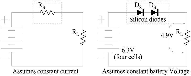
Figure 1
Linear regulators are of two general types, series and shunt. The series, linear regulator uses a series resistance that is controlled in a manner so that it drops the excess voltage from the voltage source, leaving only the amount desired for the load. The shunt regulator has a fixed, series resistance and diverts or shunts enough current to ground to bring the load voltage down to the desired value.
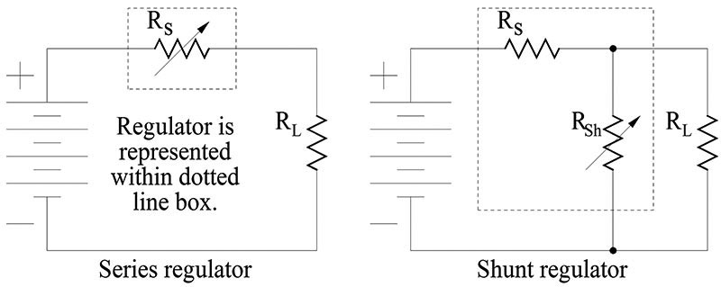
Figure 2
Another thing that must be considered when discussing efficiency is the amount of current that the regulator circuit itself needs for it’s operation. So, for instance, the series regulator circuit actually looks more like this.
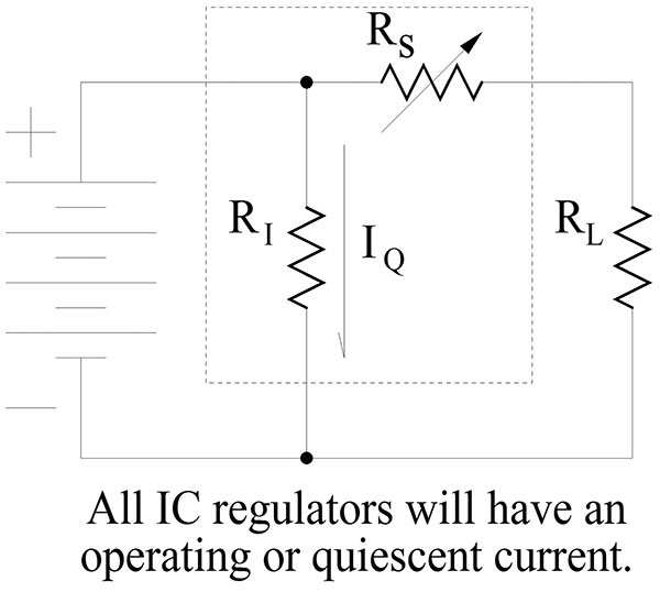
Figure 3
Assuming that a regulator is needed and sticking to linear types, there are several choices, including the zener diode and IC types mentioned in the question. A zener regulator is a very simple form of voltage regulator. The circuit looks like this:
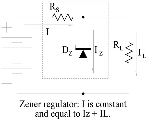
Figure 4
The theory is simple, the voltage drop across a zener diode will be constant so the series resistor drops the remainder of the supply voltage and allows the amount of current needed for that condition. The thing to notice here is that the voltage drop across the series resistor is approximately constant if the supply (battery) voltage is constant. So, according to Ohms law, the current through the series resistor is also constant. That current is the total current in the circuit and it is divided between the load and the zener diode.
The design of a zener regulator works like this:
- Find the MAXIMUM load current that will be needed. It is important to find the maximum value, because if the current ever exceeds this value, the zener regulator will drop out of regulation and the voltage across the load will be lower than the design value. This is IL.
- From the data sheet for the zener diode, find the quiescent or lowest operating value of current that is needed for the diode to operate at the zener voltage. This is Iz.
- Add IL and Iz together to get the total operating current. I = IL + Iz
- Rs must drop the difference between the battery voltage and the desired load voltage. Vs = Vb - VL. And, again using Ohms law, Rs = Vs / I
- The zener voltage of the diode is just the desired load voltage. You are probably going to have to do some rounding.
- You must calculate the worst case power consumption in both the series resistor and in the zener diode. For the series resistor this is simply Pr = Vs x I.
- For the zener diode it is when zero load current is being drawn so: Pz = Vz * I.
- It is good practice to multiple the power values by a safety factor. A 1.5X to 2X figure is generally used. The accuracy of a zener regulator can be seen on the zener’s data sheet. Look for a graph that shows the zener voltage plotted against the current. I would not be surprised by differences up to 10%, or even more. This is in addition to the tolerance value assigned to the zener diode.
A zener regulator will be as dependable as the two components used: the series resistor and the zener diode. The reliability of these will both be heavily dependent on the amount of heat generated in them. This will, in turn, depend on the safety factor I mentioned in step 8 above and also on the proper cooling of these components. A heat sink is highly desirable if the current, I is large. An IC, series regulator has a circuit something like this.
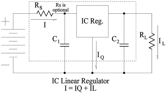
Figure 5
The design is very simple. The IC is connected in series with the power line and to the ground reference. In some cases where a different output voltage is needed, a resistor network can be connected between the IC’s output, ground, and the reference (bottom) terminal on the IC. The values of the capacitors are given on the data sheet. In the case of a battery supply, C1 can generally be omitted and a good value for C2 is often 0.1uF. Rs is an optional, series resistor that can be sized to drop part of the battery voltage when the load voltage is a lot smaller than the battery voltage. This decreases the amount of power that must be dissipated in the IC and therefore increases reliability. Again, calculations of the worst case power dissipation in both the IC and the optional Rs is needed.
If Rs = 0, then Pic = I x (Vb-VL). This calculated power must be less than the rated value of the IC package. Keep in mind that different IC packages may/will have different power ratings. Adding Rs is one way of keeping the power dissipated in the IC within this limit. If Rs is used (not zero Ohms) then the power calculations get more complicated. The value of Rs will be chosen for the maximum current situation and that will be where it’s power dissipation will be the most. Pic should also be at a maximum at that maximum current point, but I would check it at the minimum current and also around the half way point, just to be sure.
The efficiency of any linear IC regulator will be better than that of a zener regulator unless the zener is always operating with a maximum load current. When the load current decreases below it’s maximum value a zener will simply draw more current and keep the total power that is dissipated at a constant value. The IC regulator will draw a varying total current that changes as the output/load current changes. Therefore it is generally a lot more efficient.
As for life or dependability, IC regulators are generally as dependable as any other semiconductor based component. Since the current passes through them, they may be a bit more susceptible to surges than a Zener style regulator because transistors will fail faster than resistors. But if they are properly designed and installed with proper heat sinks, they can last for many decades. I would not hesitate to use an IC regulator in this application. If you want even higher efficiency, a switching regulator can probably provide that. Reliability may be somewhat lower, but not a lot.
Accuracy of IC regulators, both linear and switching, is generally excellent. They all use feedback techniques where the output is sampled to provide the correction signal to the series element which controls the output voltage. The degree of accuracy can vary with the internal circuit details, but numbers like 3%, down to 1% or even better are common. Again, as with the zener, the rated accuracy and the accuracy variation with circuit conditions are separate values so an IC regulator with a rated accuracy of 5% may be capable of holding the output value to within 1% or even better.
The LM317 that you mention is an adjustable regulator design. It requires that you use additional resistors to bias the reference pin for the output/load voltage you want. This can be an advantage if an odd voltage is needed but you can also get similar, three terminal regulators that have fixed output/load voltages and do not require those external resistors. Look at the 78xx series for positive regulators or the 79xx series for negative voltage ones.
Edward P Alciatore III
Beaumont, TX
The LM317 appears to be about 5% in accuracy (you also need to add the error from the resistors used for the adjustment, but you could get some 0.1% resistors to manage that). A quick look on digikey shows plenty of 1% zeners so that path may offer more accuracy.
If your load is fairly constant, your zener circuit can be tuned so the zener will just barely turn on with the expected load. But if the load goes down, the zener will eat power to keep you regulated. There are some other parts out there that offer better accuracy. Check out the LT1460: 0.125%! (but only ensures 20mA output)
Kevin Cutts
Lake Zurich, IL
The LM317 would create a more accurate voltage; however, that may not be the best way to go. Not knowing what voltage in and voltage out you have, it’s hard to say, but the LM317 will scrub off the excess voltage as heat. However, there are boost/buck converters available for not much money (I bought four little boards based on the LM2587 for about $7.50 each off eBay, for instance) that will conserve the current (minimal heat, minimal waste, minimal extra battery usage) and keep the voltage even more accurate.
For perfect usage, team one of those up with a zener secondary regulator, so that you have a minimum of wasted current through the resistor feeding the zener and your circuit; that way you have both worlds working for you.
Ralph Phillips
Shreveport, LA
3-terminal voltage regulators, such as the LM317, are very accurate, and are suitable for most applications. You might want to consider a fixed voltage output, low drop-out type, 3-terminal regulator such as the 78L00 series, made by several different manufacturers. The low drop-out minimizes power loss — for example, you can obtain 5 volts out from 6 volts in (4 x AA batteries). However, the purpose of any voltage regulator is to create a stable fixed output from a variable input. Thus the regulator must dissipate power, and you must observe the power rating of the regulator, or it will overheat and self-destruct.
Bob Stewart
Mancos, CO
Are you looking for stability or reliability? The battery is reliable but not so stable because the voltage drops as the charge is depleted. If you have a full time battery charger attached, the stability problem goes away. The zener diode has a rather high impedance, up to 100 ohms for those under 6 volts and lowest at 6.8 volts. If you have a 6.8 volt zener running at 20 mA with an impedance of 25 ohms, and the load varies 10 mA, then the voltage will vary: delta V = Ro * delta I = 25 * .01 = 0.25V. The LM317 on the other hand has an output impedance in the order of .05 Ohms and you can set the voltage as accurate as you need using the schematic on Figure 5 of the data sheet. The voltage should stay within 1% over time but you can reset it periodically if you want. You should have a minimum load of 10 mA on the LM317 for good stability and don’t run at max current if you want good reliability.
Russell Kincaid
Milford, NH
I would like to experiment with high voltage projects, but all my experience in building power supplies is for low voltage (typically 5 or 12 volts). I’d love a schematic for a high voltage power supply that could produce between 0 and 250 volts safely. Also, any safety pointers for getting started would be appreciated.
#3171
Ed Warren
Everett, WA
Please log in to post an answer.
Answers
It is my understanding that "Variac" type transformers do not provide isolation from the input power. They are basically tapped coils. In order to safely provide isolation they must be connected through a 'true" transformer. Depending on output stability requirements, you may be able to use a Cockroft-Walton voltage multiplier circuit through an isolation transformer. Check Wikipedia for "Cockroft-Walton" and "autotransformer."
Karl Aderer
Bay Saint Louis, MS
You want to be extremely cautious experimenting with high voltages as they are lethal and can be fatal. Rather than trying to construct a high voltage supply, which could be dangerous, you might consider a variable transformer such as the Volteq #1KVA_110V/250V (www.volteq.com), which costs about $70. This transformer plugs into a standard 120 VAC outlet and provides an adjustable output from 0 to 250 VAC, and provides isolation from the AC power grid. If you want DC voltage, you can construct a simple bridge rectifier circuit. However, there are many more interesting projects that use 5 - 12 volts, and I suggest you pursue some of them instead.
Bob Stewart
Mancos, CO
Correcting Bob Stewart's answer: The variac he mentioned "VOLTEQ 1KVA VARIABLE TRANSFORMER VARIAC 1000VA 0-250V 110V INPUT" does NOT provide insulation from AC, as confirmed by Volteq. I suggest connecting such a variac only to an outlet with a Ground Fault Interruptor (GFI).
Oskar Leuthold
Santa Cruz, CA
You didn’t indicate how much current you are expecting from the supply? Searching the internet I found the referenced schematic for a 300 VDC variable voltage supply that will deliver up to 100 ma. Circuit is for 220 VAC mains but we can substitute a step up transformer for operating with a 120 VAC mains. I have attached a parts list reference from Digikey that should do the trick. Due to the high voltage involved, you should put the components inside an enclosure, such as a Bud Industries box and bring the output up to a couple of banana type jacks or terminal block. You can also mount the pot on the outside of box and add a knob to it. Transformer is the most expensive component and can be sourced from other suppliers if you need to reduce costs. Hope this helps!
Schematic: www.eleccircuit.com/the-variable-high-voltage-power-supply-0-300v/
Parts List: www.digikey.com/short/327wpp
Doug Foreman
Warren, MI
Does anyone have suggestions for buying or building a vehicle detector which can be used with the Arduino? I wish to sense and count passing vehicles.
#2175
Robert Johnson
Bolton, MA
Please log in to post an answer.
Answers
I would try either a magnetic field disruption sensor (long iron core coil monitored by a hall effect sensor) or a security type passive infrared detector (frequently available cheaply from electronic surplus outlets).
Karl Aderer
Bay Saint Louis, MS
A couple of years ago I wanted to know how many cars were driving past my house each day so I built a counter for about $140. Here is the link to the 12 minute Youtube video describing how I did this: www.youtube.com/watch?v=Tw0P2DtB8Yo.
In addition to the car count, the laser detectors that I used also allowed me to acquire direction and speed. I saved the data to a SQL server and rendered the data on a webpage using highcharts (details in the video). This required a PC to be running all of the time (about 90 watts). I have now replaced the PC with a Beaglebone Black and use a MQTT listening service called mosquitto to acquire arduino data and pass it to the mysql database.
Programming and rendering is being done with Node-Red. I hope to develop a video with that configuration soon. Best of luck and please let me know if you have any questions.
Jeremy Lang
Madison, WI
This has been done before by several folks using a tube counter approach. The drawback is that you need to lay a tube across the roadway, but if this is OK for your project, this is the way to go. It’s the same way that professional traffic counts are often done. Two links on projects are https://hackaday.io/project/4567-traffic-counter-road-tube and www.tomorrow-lab.com/lab16.php.
Ultrasonic sensors might work if you you can put the sensor very close to the lane in question (e.g., if you just need to detect traffic on the nearest lane). Otherwise range becomes an issue and cost increases for longer range sensors. This site has a project that did just that: www.chris-sheppard.com/?page_id=40.
Radar rangefinders are the next step up for range if you can’t use a tube, one example would be something like the LIDAR-Lite 3 Laser Rangefinder, but you’re now using a >$100 sensor. There’s 3 pages of discussion on this topic on the arduino forum: https://forum.arduino.cc/index.php?topic=298000.30.
Mike McGurrin
Vienna, VA
I replaced some outside 60W bulbs with CREE dimmable LED replacements. The lamps are controlled and dimmed using X10 switches. When switched off, the lamps still glow at about 20% and will not shut off completely unless I use the disable feature of the switch. However, this prevents the timer from automatically controlling the lights. What causes this and is there a fix, or are LED replacements not compatible with X10?
#2174
Christoffer Mortensen
Piscataway, NJ
Please log in to post an answer.
Answers
They're compatible; what you're seeing is the leakage current on the output of the X10, which is still enough to cause the LEDs to light up barely (and which isn't visible on incandescents.) If you truly want the LEDs to go out, though, you'll have to look for something better than the old X10 designs.
Ralph Phillips
Shreveport, LA
LED's use much less current than incandescent bulbs. Even just a few milliamps of leakage current through the X-10 modules can be enough to keep them glowing quite a bit. As a workaround, I've gotten around this problem by putting a low wattage (like 15 watts) incandescent bulb into a second socket.
William Barnett
West Haven, CT
Conventional x10 switches require a small current to run through the load (i.e. an incandescent light) in order to work correctly. For non incandescent loads such as CFL or LED lights you need a x10 switch specifically made for them. I currently use a WS13A x10 wall switch and also an XPFM x10 fixture module to switch LED lights (and CFLs). These x10 switches are not dimmable though. In general, LED lights need a dimmer specifically made for LED lights. I have had a good success with Lutron CL digital dimmer (e.g. MACL-153MH) as a manual dimmer but I do not know of an x10 compatible dimmer designed for LED lights. Perhaps someone else knows of one that will work.
Dan Koellen
Roseville, CA
I go through this problem whenever I use x10 in a small project. x10 appliance modules need some kind of load resistor, but due to the 110VAC appearing when it turns on, I do not advise it. Instead, a batter way to solve it is to connect a 110VAC relay parallel to the LED bulb. If you want to use a resistor 33K 1W will be OK (I tested up to 42K that works), BUT be very careful about insulating the wire leads. I tested both methods (resistor turn on only a second in on state), they work perfectly.
Ankur M Bhakta
Tulsa, OK