With Russell Kincaid
MIXER CIRCUIT
Question:
As you may know, dual gate JFETs/MOSFETs have been phased out, and those that can be found are very expensive. Somewhere I have seen a circuit that duplicates, say a 3N201 or a 40573 being used as a mixer in a receiver, using two MPF102s. I would appreciate a circuit, if possible.
— Barry J Maloney
via email
Answer:
I was not aware that dual gate FETs were being phased out. I think it is that thru-hole parts are not in demand because the electronic world is going to surface-mount. I found three dual gate MOSFETs presently available: BF1211, BF908, and BF991, all in SMD packages.
A mixer consists of a non-linear device which handles two signals of different frequency. The output has the original two signals plus the sum and difference frequencies. A filter is required at the output to select the desired frequency, usually the difference frequency. A diode makes a good mixer but the best you can do is -6 dB gain from RF input to IF output. An XOR logic gate can also be used as a mixer within its frequency range.

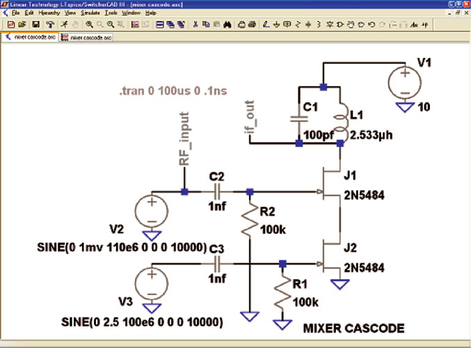
FIGURE 1.
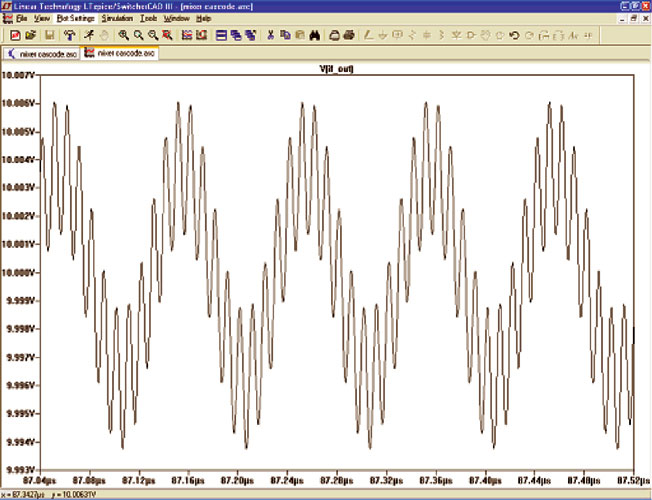
Your request for a two transistor circuit brought a cascode circuit to mind, so I threw together the circuit of Figure 1 in the LTspice simulator. The RF input to J1 is 2 mV peak-to-peak at 100 MHz; the local oscillator (LO) input to J2 is five volts p/p at 110 MHz. The output circuit is tuned to the difference frequency of 10 MHz. Figure 2 is the output signal. The 10 MHz is about 70 mV p/p, a gain of over 30 dB. The LO output is significant, more filtering is needed.

FIGURE 2.
A single transistor can be used as a mixer and oscillator at the same time, but the problem is that a strong RF signal can “pull” the LO off frequency, causing increased interference and reduced gain. This problem increases as the RF and LO signals get closer together.

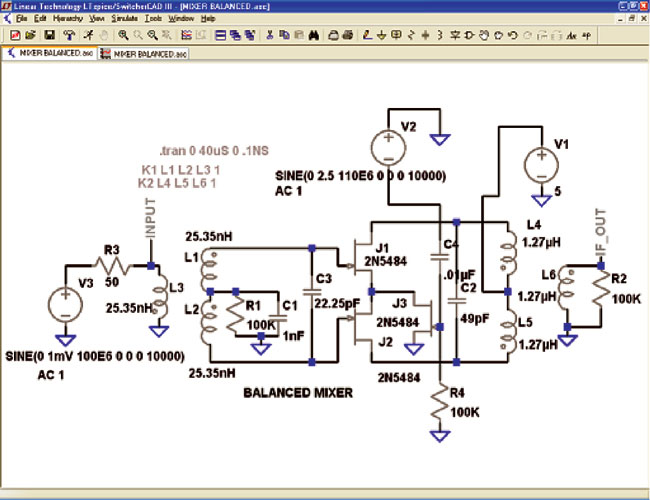
FIGURE 3.
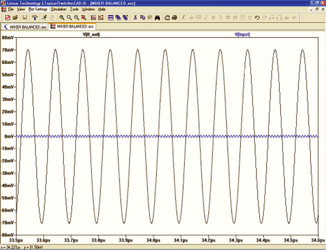
There is a lot of interest nowadays in balanced mixers which will reject the LO signal, making the output filtering easier. A single balanced mixer rejects just the LO, a double balanced mixer rejects both the RF and the LO. Figure 3 is a single balanced mixer. The input transformer is center-tapped to provide push-pull drive to the output transformer, through the JFETs. The local oscillator drive is common mode and does not couple to the output. The output transformer must be well balanced, such that when the same signal is applied to both sides, the result is cancellation. As you can see in Figure 4, there is no LO in the output waveform. The 10 MHz is 70 mV peak, a gain of over 36 dB.

FIGURE 4.
I used the 2N5484 because it was in the library; it is similar to the MPF102, and costs 11 cents.


Comments