With TJ Byers
Full Range Dimmer/Speed Controller
Question:
I need a 12-volt, 12-amp PWM motor speed control that lets the motor come to a dead stop when the speed control is wound all the way back. I could use a switch-pot to totally remove power, but wondered if there is a way to make the PWM control go from 0% to 100%. Most PWM controllers seem to go from around 5% to 95%.
Donald J. Johnson
via Internet
Answer:
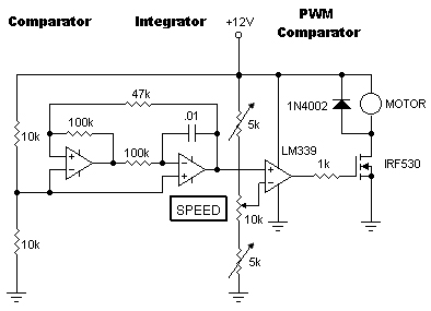
You're quite right. Most motor speed controllers and lamp dimmers are built around a 555 timer that's operated in the PWM mode, which has a range of 5% to 95%. Before the 555 became popular, we used the circuit shown below
.
This design uses a triangular wave generator and a comparator to create PWM (pulse-width modulation). It goes like this. Two op-amps use a positive feedback loop that's closed around a combined comparator and integrator. When power is applied, the comparator assumes one of two states; for the sake of this discussion, let's call it high. This output is applied to the integrator which begins to ramp down by charging the .01µF capacitor. When the output voltage of the integrator reaches a threshold voltage on the positive set by the 47K and 100K feedback resistors, the comparator switches from high to low which, in turn, causes the integrator to start charging the capacitor in the opposite direction. This cycle repeats endlessly and outputs a clean triangular waveform.
The triangular wave is applied to the positive input of the PWM comparator. The SPEED control sets the trigger point for this comparator. When threshold voltage is greater than the peak voltage of the triangular wave voltage, the duty cycle is 0%; when the threshold voltage is equal to the peak-to-peak triangular voltage, the duty cycle is 100%. The 5K trimmers are used to set the range of the SPEED control. Any op-amp will work in this circuit, including the ubiquitous 741. BTW, as an afternote here, I was pleased to find this design still live and well at G. Forrest Cook's web site (www.solorb.com/gfc/elect/solarcirc/pwm1/).


Comments