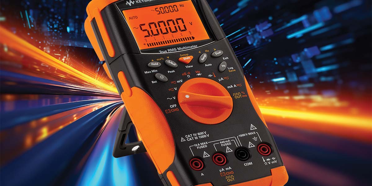
By extending the life of a multimeter with a faded OLED screen with the help of Python and an Arduino, we’ve created a multimeter-based data logging system, with the multimeter functioning as a high-end measurement engine.
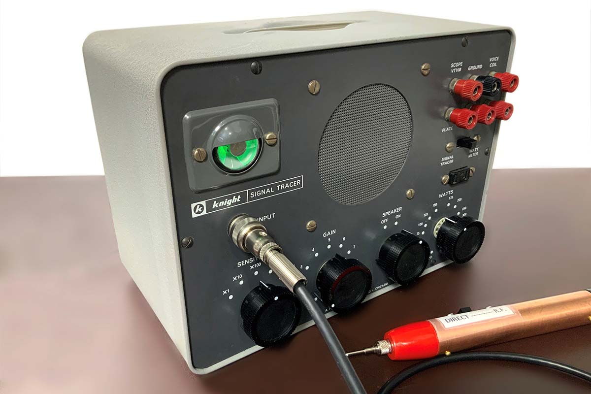
The majority of diagnostic and alignment tools I use for my refurbishing projects are vintage instruments themselves.
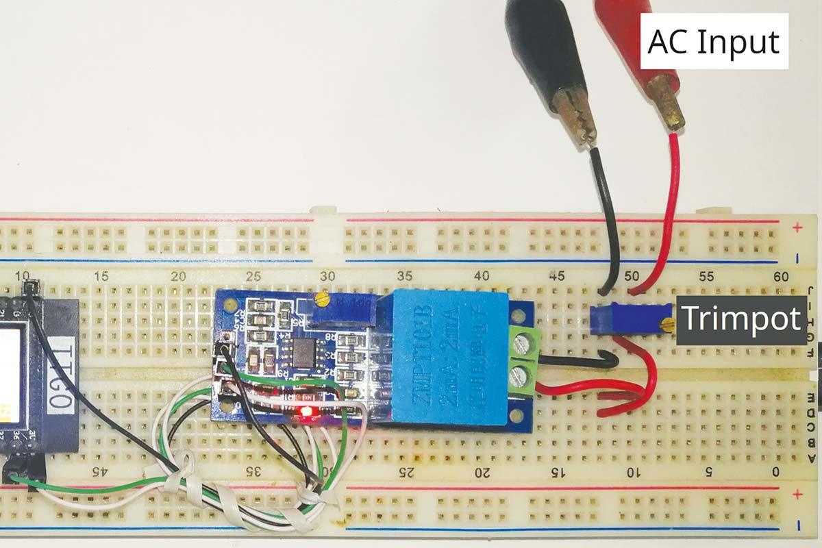
Multimeters are a wonderful and easy-to-use tool to accurately quantify the incoming AC voltage from a pure sine wave output power supply. Barring a few high-end hybrid models, not all are capable of plotting the trend of this quantity over a limited time period, like an oscilloscope. So, I decided to build a voltage monitoring system with RTOS.
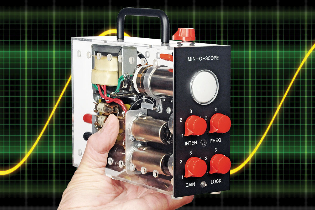
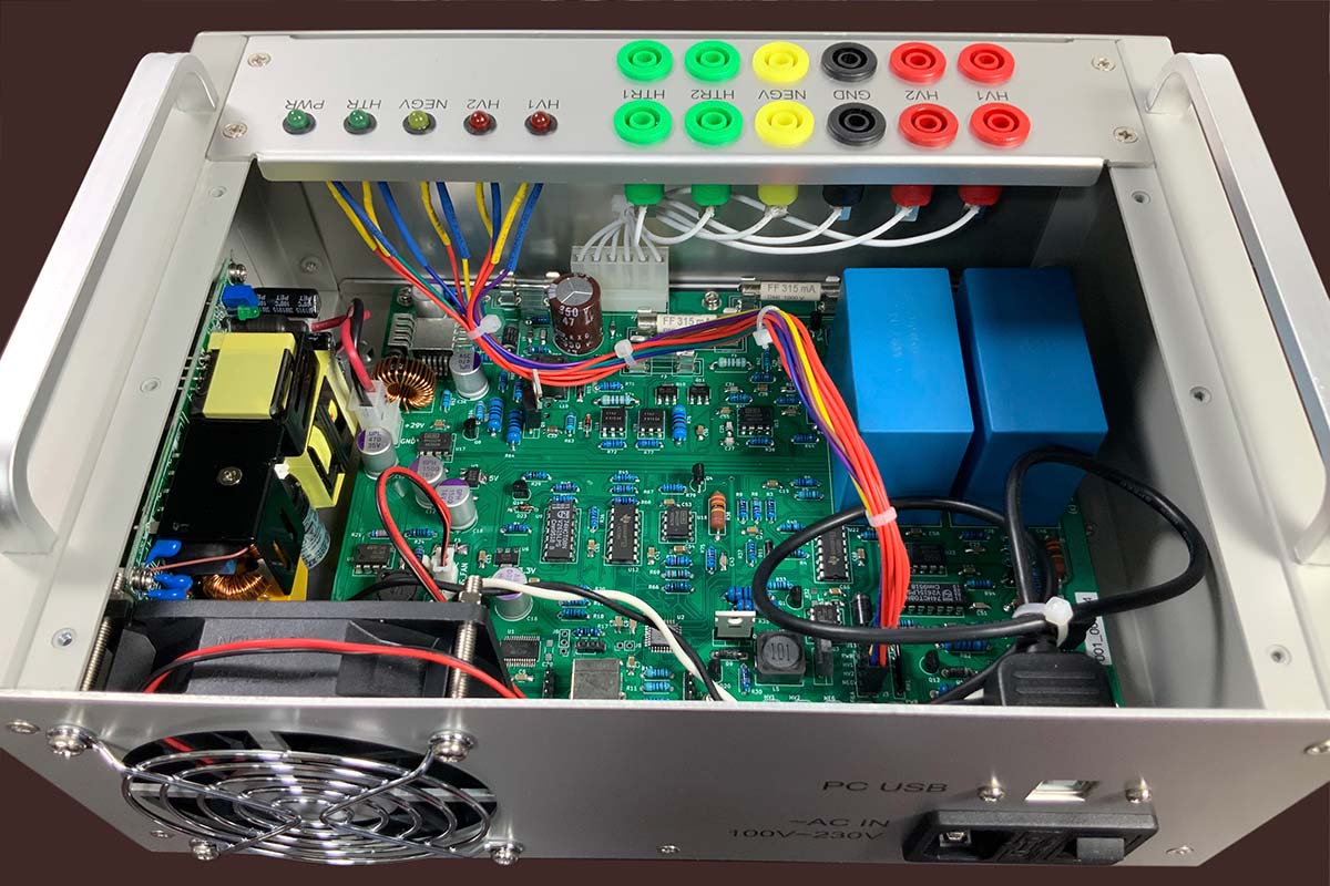
What could be more fun than building a miniature oscilloscope? Not one with an LCD screen, but a scope with a real live cathode ray tube just one inch in diameter. All the parts -- including two 6AU6 vacuum tubes -- will be housed in a 5” x 7” x 2” box.
This modern take on the tube tester is a must-have for anyone who regularly works with tube-type electronics.
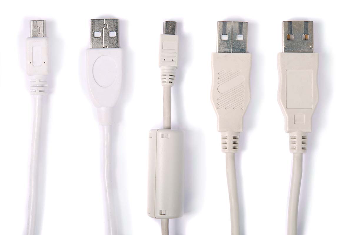
If you’re like me, you likely have a drawer or shoe box stuffed with assorted USB cables that are used to either charge or program a USB device. The problem often is that some cables may only be useful for charging, and which only have the +Vcc and ground wires intact with one or both data wires either broken or not connected in the first place. Here’s a simple test jig to help you tell what’s what.
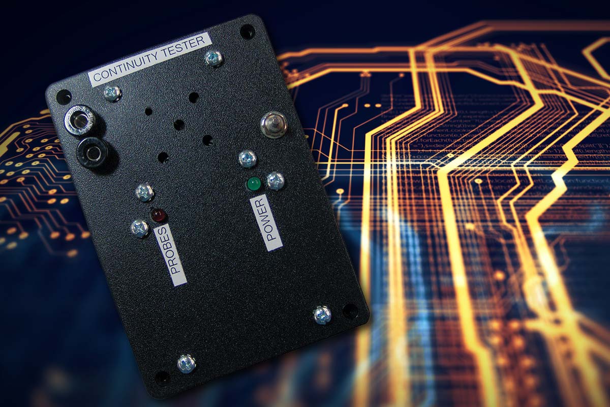
During a recent vacation, I challenged myself to come up with a design for a continuity tester that suits my particular testing requirements. Most of the time, I go straight for a microcontroller, but this time I decided to use only non-programmable components. I also decided to use only through hole components, to make soldering easier.