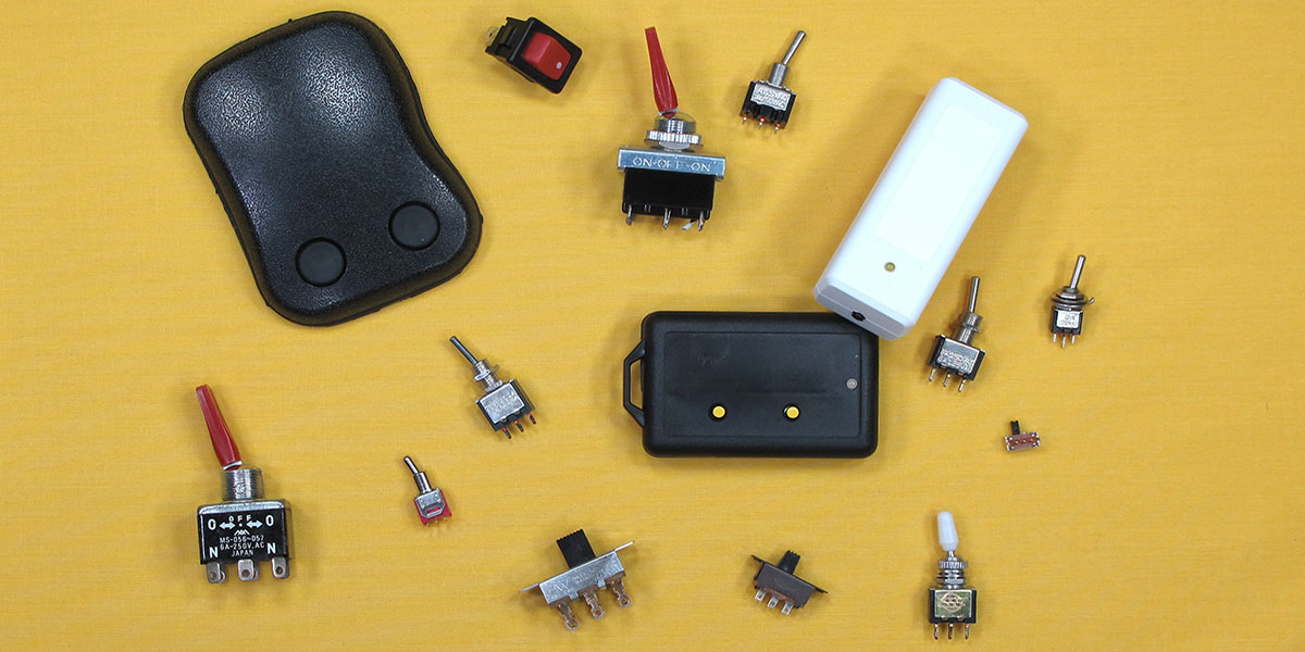
Use a Pushbutton to Turn Your Devices On and Off
Most electronic devices today have a single button you push to turn them on and off. Think of your cell phone, laptop, and even your TV. There is no toggle to flip, no knob to turn back and forth, nor slide switch to move. So, how do you get one of these power buttons into your project so your latest gadget can sit next to your other devices without the embarrassment of a toggle or slide switch?
Microprocessors drive most of our devices, and many of these processors have the ability to go into a low power sleep mode. In this state, the processor can still respond to an external signal such as a button press. When you combine that with some circuitry to control power to peripheral devices such as displays, radios, and servos, you have a system that can turn itself on and off without much additional hardware. The December 2013 issue of Nuts & Volts described an add-on solid-state power switch from Pololu which performs a similar function. As a regular customer of Pololu, I have been aware of this module for a while. However, I wanted a cheaper, more flexible, and integrated solution that wouldn't require me to stock another part. If you're using a microprocessor and you're in control of the hardware and software design of your system, you can get this power control capability at little to no extra cost in money or board space.
I’ve been working with Microchip PIC processors for quite a while, and their eXtreme Low Power (XLP) processors have some impressive low power sleep modes — with some claiming 20 nano-amps (nA). This makes them ideal for battery-powered devices. Okay, but what does that mean in real life?
We need to do a little math to get some perspective. Let’s say the design goal is to run the device off two AAA alkaline batteries for at least a year. The actual run time of a wireless doorbell transmitter, for example, is calculated as 1,000 rings per year, with each ring lasting a generous four seconds and drawing 25 mA. That comes to a total of roughly 28 milli-amp hours (mAh). The total capacity of these batteries ranges from 800 to 1,200 mAh, so we can easily operate the doorbell for several years.
Now, we need to worry about the current draw while the doorbell is idle. If our circuit at idle draws 1 micro amp (uA) or less, then the batteries will last roughly 800,000 hours. With 8,760 hours per year, this is about 90 years. At a sleep-mode draw of 20 nA, we’re talking about 50 times longer!
So, if the specs are correct, then putting our processor and the rest of the device into sleep mode should not appreciably deplete our batteries. The shelf life of alkaline batteries is only 10 years, and most gadgets don’t stick around for even that long — with garage door openers and alarm sensors being the exception. For now, on paper, the numbers look promising, and if the spec sheet writer hasn’t misplaced a decimal point, we can use a low power microprocessor to switch our device on and off.
Design and Testing
A simple pushbutton operated LED is used to test this. I only needed a few parts (which I had on hand), a voltmeter, and David Jones’ µCurrent (see sidebar) to verify I’m drawing very little current when I’ve turned the system off. Figure 1 shows the test circuit.
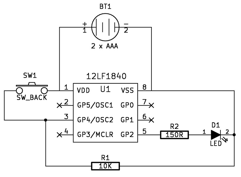
FIGURE 1.
You can see that the processor is permanently connected to the battery. The power switch is between the battery and one of the processor input pins. Figure 2 shows the prototyped circuit (with a few extras) connected to my current measuring system.
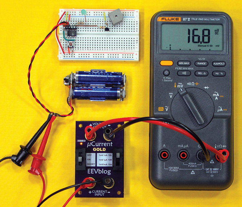
FIGURE 2.
The meter shows that in sleep mode this circuit draws 16.8 nA. The code for the power switch is written using the CCS PIC® C compiler, and the entire file can be obtained from this article's download link. Portions are duplicated here to explain how the switch works.
The power switch uses two key features of the processor: 1) the low power sleep mode; and 2) a “wake on interrupt” which can come from a voltage change on any of the I/O pins. These features can be found on microprocessors from many different manufacturers (not just those from Microchip). Starting from sleep mode, the general operation is as follows:
- The user presses the power button.
- The processor detects the change from low to high on a pin and wakes up.
- The processor goes on to initialize itself and continues to perform its main task which, in this case, is to turn on an LED.
- The main processing loop checks for a button press of a certain length of time (two seconds, in this case). This can be with the same button that turned the system on.
- Once that button press has been detected, the processor turns off all peripherals, sets up the conditions to detect the next “power on” event, and goes to sleep.
Let’s look a little closer at how this happens.
The system doesn’t start out in sleep mode. When it first gets turned on (for example, when we put in new batteries), we don’t want it to interpret this as a start signal. Fortunately, the processor can determine how it got started.
One of the first commands executed after startup is:
if( restart_cause() == NORMAL_POWER_UP ) HWSleep();
This essentially asks, “What woke me up?”
There can be several reasons for a processor waking up; the two we are concerned with are NORMAL_POWER_UP and RESET_INSTRUCTION. When we connect the battery for the first time or replace the batteries, the processor wakes up and detects a NORMAL_POWER_UP as the reason. The code then tells it to go to sleep since we only want it to turn on after a reset that was initiated by a button press.
The function HWSleep() prepares the processor for the lowest possible power consumption, sets up the interrupt, and puts the processor to sleep:
void HWSleep( void )
{
//— power down what we can...
setup_adc_ports( NO_ANALOGS );
setup_vref( VREF_OFF ); // uses 16uA when on
setup_timer_1( T1_DISABLED ); // turn off timers
setup_timer_2( T2_DISABLED );
output_a( 0x00 ); // turn off everything
output_high( PFET ); // set high to turn off pFET
enable_interrupts( INT_RA4_L2H ); // turn on interrupt on power button
sleep(); // go to sleep
// Wakeup from sleep resumes here...
clear_interrupt( INT_RA4_L2H ); // clean up interrupt from sleep
disable_interrupts( INT_RA4_L2H );
reset_cpu(); // do a full reset when we wake up
}
All the instructions up to enable_interrupts() are designed to eliminate any current leakage through the processor, and to turn off power to peripheral devices. The specific instructions will depend on the internal and external peripherals, special features of the processor, and so on. The spec sheet has all the information you need. However, you may need help from user forums and other documentation to make sense of it, and some of it is just trial and error.
For example, I had a serial connection I was using for debugging, and I just couldn’t get the current draw near to what I was expecting. Once I disconnected the serial cable, all was fine. So, for those applications that have a serial connection built in, you need to add additional commands to be sure it doesn’t draw power from the processor during sleep mode.
The enable_interrupts() instruction tells the system which pin will be used to wake it up, and the next instruction puts it to sleep. When the selected pin detects a change (in this case, a transition from low to high), the processor wakes up and resumes processing from the point at which it went to sleep.
Then, we clean up our interrupt handling and force a restart of the processor, so it can start fresh by going through a complete system setup.
When it encounters the check for why we started up, the reason will be RESET_INSTRUCTION, and processing will continue to turn on the LED and then into the infinite loop that is the basis for most embedded systems. Within that loop, we check for a button press of two seconds or longer which initiates the HWSleep() function all over again.
The additional hardware on the prototyping board represents control of power to a load (in this case, a buzzer) via a pFET (P-channel MOSFET). Support for this is included in the code file (LF18Switch.c) at the article link.
Applications
Using a microprocessor as a power switch may seem like over-kill, however (as I mentioned earlier), since my projects are usually processor-based, I get the functionality for free. Even the pin for the button is free because I can use it for other operations after the system is turned on. While some systems — such as our LED light — need a switch to turn off, others will turn themselves off automatically after they have completed their tasks. We’ll see that in my wireless doorbell and motion sensor transmitters next.
Before we get to that, there are some other tests I want to perform. Turning an LED on and off is a great proof of concept, but I need to do some real work. In Figure 3, I show a relay and some other peripherals added to the original circuit.
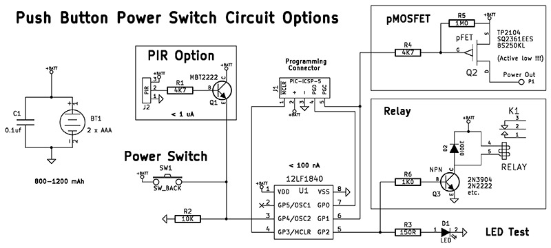
FIGURE 3.
A transistor-driven relay allows us to control large loads. Beware that when the system is on, the relay represents a significant load, and unless it is turned on only briefly, is not suitable for a small battery-powered system. No change is required in the software to use a relay instead of an LED.
For driving relatively low power (200 mA or less) loads, I prefer to use a pFET. They’re cheaper than a relay, use very little space, and can have a very low voltage drop. Driving a 20 mA radio transceiver, I experienced a “diode forward voltage drop” of only 0.15V. Ordinary transistors will usually have a drop of 0.7V or more. The 2N2222 I tested had a 0.9V drop with the same 20 mA load I tested with the pFET.
For my application, I need to get the highest possible voltage from the battery to my radio. The circuit for this is included in Figures 2 and 3. Note that the pFET is active low. You need a 1M pullup resistor (R5) to ensure it turns off because the output from the processor will float when it’s asleep.
The reason I’m focused on low sleep currents and pushbutton activation is a wireless doorbell and alarm project I’m working on. I want to be able to use a pushbutton switch or a PIR (passive infrared) sensor to trigger the radio transceiver that communicates with the base station. The radio takes a while to power up, so if you just connect the pushbutton between the battery and radio module, and then tap the button, the circuit may not be on long enough to power-up and send the signal. I need to be sure the transceiver has enough time to fully power-up, send a signal, then continue to stay on long enough to receive a confirmation signal. This, in turn, lights the doorbell button to let the user know the bell has actually been rung.
The processor provides the necessary logic and timing. In this particular scenario, the pushbutton is only used to turn the system on. Once the processor has performed its tasks, it goes to sleep on its own, waiting for the next visitor.
The entire package fits into a plastic single-gang junction box behind the doorbell button. When idle, the circuit draws less than 50 nA. On average, the system is powered to 20 mA once a day for only a few seconds. The batteries will easily last more than a year, which was the design target.
Figure 3 includes a PIR motion sensor trigger circuit for the same wireless doorbell project. I have several transmitters, and the receiving base station plays a different tone depending on which transmitter is triggered. Panasonic makes a low power PIR motion sensor that draws less than 1 uA while waiting to detect motion. When motion is detected, the signal is amplified by an NPN switching transistor that, in turn, triggers the interrupt on the processor, waking it up.
In addition to driving the radio with the necessary timing, the processor has some delays built into it so the receiver isn’t constantly ringing while something is passing the motion sensor. The radio is turned off during these delays. Figures 4 and 5 show the front and back of the wireless motion sensor module.
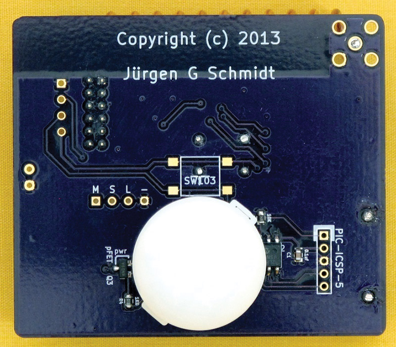
FIGURE 4.
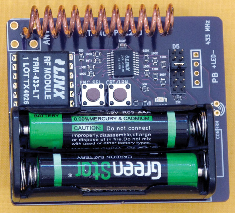
FIGURE 5.
The front has the radio, antenna, and battery pack. The back has the PIR sensor, power control, and processor. This is designed to be mounted discretely in a junction box with only the sensor dome exposed. I used OSHPark (see References) to manufacture the circuit board. Assembly is done via my toaster oven reflow system.
I hope this has inspired you to “toss the toggle” and include a pushbutton power control into your next project. While I have focused on a particular microcontroller and compiler, these principles can be applied to other hardware and software development systems. NV
PARTS LIST
| DESIGNATOR |
PART |
CATALOG PART # |
| (All part numbers are for Mouser Electronics.) |
| U1 |
PIC12LF1840 |
579-PIC12LF1840-I/P |
| Q2 |
pFET TP2104 |
689-TP2104N3-G |
| PIR |
Panasonic |
769-EKMB1103111 |
| The other parts are miscellaneous workbench supplies. |
Measuring Microamps and Nanoamps
In the course of working on this project, I discovered that measuring current in the micro-amp and nano-amp (nA) range is no easy task. Most digital voltmeters can measure milliamps. However, measuring anything below that with accuracy is difficult. Even my multi-hundred dollar professional multimeter was not up to the task. To verify that my circuit was truly drawing a microamp or less, I needed a reliable measuring device.
In researching for a solution to this, I discovered a device made by David Jones in Australia. If you have been learning about electronics for a while, you may have come across one of David Jones' enthusiastic videos on YouTube or his video blog. He has over 600 videos covering basic electronics, how to use your oscilloscope, product reviews, and more. I've learned a lot from him over the years.
In 2009, David Jones presented the open source µCurrent, and described both the need for it and how to make it in an article in the April 2009 issue of Silicon Chip Magazine. The µCurrent is a low cost (less than $100) adapter that lets you accurately measure current down to the nano-amp with any digital multimeter capable of measuring millivolts. In 2013, Jones announced the version 5 µCurrent Gold and initiated a Kickstarter project to fund production, exceeding his funding goal more than ten-fold. His video on the Kickstarter page does a good job of explaining why you need something like the µCurrent to measure current without impacting your circuit.
He is currently in production, but it may still be a while before units are available in the US. I wasn't prepared to wait, so I downloaded the publicly available PCB manufacturing files and parts list. I made some changes to the PCB files so they would be accepted by OSHPark, and I checked with David Jones about substituting for a part that was only available in full reel quantities. All of the parts were available from Mouser Electronics. Once the boards came back, I assembled my own µCurrent and sent David Jones a donation. You can see the bare boards and my assembled µCurrent in Figures A and B. The µCurrent uses several precision op-amps and precision resistors to generate a voltage in the millivolt range that is proportional to the current being measured. The µCurrent can be seen in action back in Figure 2. The 16.8 millivolts displayed on the meter translates to a measurement of 16.8 nA for this circuit in sleep mode. I'm using a PIC12LF1840 microprocessor, and the spec sheet says the sleep mode current is 20 nA. For anyone working with low currents, a tool like the µCurrent is indispensable.
See the References section for more information about David Jones, the µCurrent, and the vendors I use.
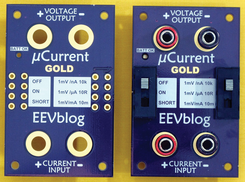
FIGURE A.
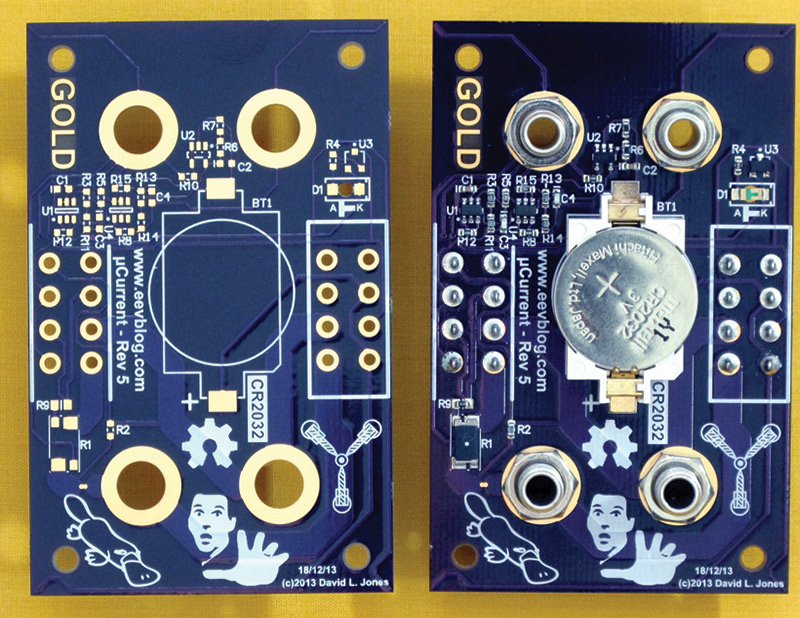
FIGURE B.
References
Vendor Websites:
CCS PIC® C Compiler
www.ccsinfo.com
OSHPark PCB Manufacturing
oshpark.com
Mouser Electronics
www.mouser.com
Microchip
www.microchip.com
Documentation:
David Jones Video Blog — 600+ videos!
www.eevblog.com
Microchip Tips & Tricks Guide; Section 2 addresses low power issues
ww1.microchip.com/downloads/en/DeviceDoc/01146B.pdf
Microchip Low Power Design Guide is a bit more technical
ww1.microchip.com/downloads/en/AppNotes/01416a.pdf
David Jones' µCurrent current adapter for multimeters
www.eevblog.com/projects/ucurrent
µCurrent Gold Kickstarter Project
www.kickstarter.com/projects/eevblog/current-gold-precision-multimeter-current-adapter
Adafruit µCurrent listing — an excellent short description
www.adafruit.com/products/882
Downloads
What’s in the zip
Source Code - LF18Switch.c

