Even when a circuit functions as it’s supposed to, it’s not always easy to tell what it’s doing. Plus, waiting for an output (especially if there’s a long delay involved) is not always practical. Conversely, if a circuit does not function, the only means to find out what’s wrong is to troubleshoot it with either a multimeter or oscilloscope. Wouldn’t it be great if the circuit itself could tell us more directly what’s wrong?
This is solved, in part, by a light that turns on with an on-off switch. For simple circuits, that might be enough — especially when considered from a manufacturing standpoint. A manufacturer needs to keep costs as low as possible, which means keeping the parts count low. So, you don’t often find things like extra LEDs that show what’s happening when dealing with a circuit you’ve bought.
Unfortunately, for more complex circuitry, the single power-on indicator (Figure 1) is not going to be enough to indicate what’s happening.
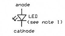
FIGURE 1.
While this might not be an issue with a project that works (as long as it keeps working), circuits that need troubleshooting will need to provide more information. Let’s take a closer look at how and where to add LEDs that can provide the help that we need.
Even a simple “power on” LED can be misleading. For example, if your power supply’s power-on indicator is lit, it doesn’t mean your downstream circuit is getting power. Anything from faulty connectors, cold solder connections, a break in the wiring, and the on/off switch can be the guilty culprit. (That’s why I’ll install a power-on LED to the main power traces on the circuit board itself instead of at the power switch.)
The next step is to make sure we’re getting any external signals that our circuit needs to do its thing. Is the incoming signal positive or negative logic? Depending on whether or not the input signal can handle the drive current (typically 20 mA drive current required by LEDs), a driver is needed. Schematic 1A shows the wiring for positive logic.
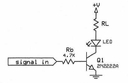
SCHEMATIC 1A.
A logic “1” will cause the LED to light, while Schematic 1B shows requirements for negative logic by using Q1 as an inverter while Q2 drives the LED.
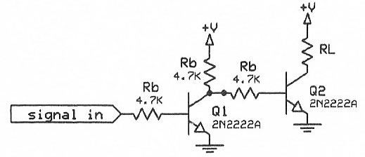
SCHEMATIC 1B.
The same technique may be required downstream, depending on where we tap a signal from. For example, the 555 timer — capable of 150 mA of source or sink current — can drive the LED and current-limiting resistor directly. Refer again to Schematics 1A and 1B.
The same technique can be applied to other points in a circuit; for example, a clock circuit used for timing. A blinking LED will show that other oscillators are working, while a solid on or solid off LED will show that the timer is either not working or held in “RESET” mode (see Notes). Schematics 1A and 1B can be added at any point in a project where we want to check for a signal.
To avoid confusion, using different colored LEDs and labelling them on the front of the box housing the circuit will provide an overview of operation.
When a single indicator is not enough — like when there are a lot of individual LEDs, we need to check if a counter is operating correctly, or if we need to count events (like how often a circuit performs a given operation) — we need to upgrade to the next level by providing a numerical display of what’s going on.
If we look at multiple LEDs indicating several different actions taking place in our circuit, these multiple signals can be seen as a binary word. For example, if the circuit is on and in standby mode, the inputs of single LEDs are lit in such a way that they represent either a binary “1;” for actual operation, a binary “2;” invalid (or no) input, a binary “3;”a non-functional digital timer, a binary “4;” and so on.
When these signals are fed into U1 (a 14511 seven-segment latch/decoder/driver) of Schematic 2, the seven-segment display will show the appropriate number. This is much easier than having to glance over a multitude of separate LEDs! This method can also be used to indicate the position of a rotary switch. One example of this application is adding a digital channel display to an older CB radio that’s been converted to 10M or 12M.
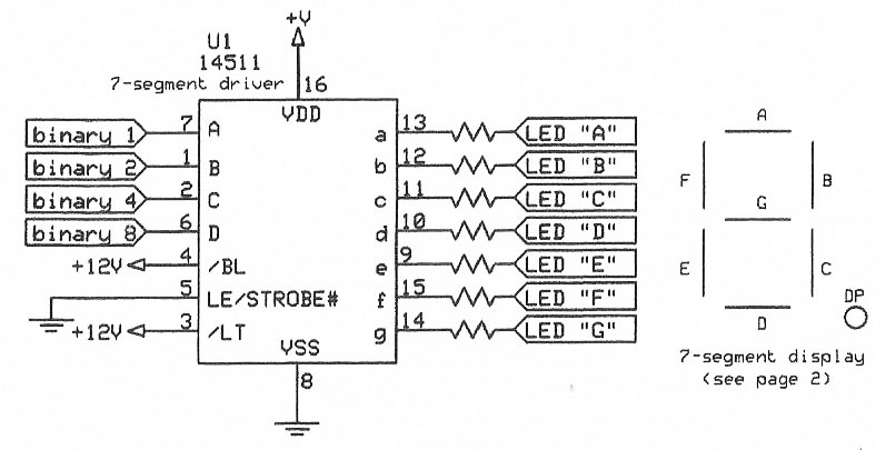
SCHEMATIC 2.
To develop this idea further, to where our LED circuit does the actual counting, a 14516 (binary up/down counter) can be added (Schematic 3).
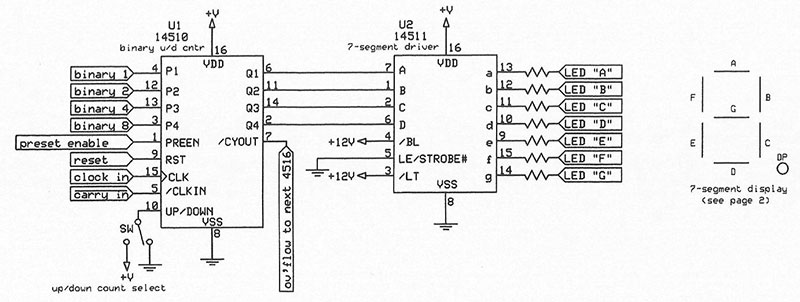
SCHEMATIC 3.
Depending on how it’s wired, this IC can count either up or down. It also has the capability to be preset to a particular number if needed.
This application is great for counting events, and is of particular use when the events happen faster than the human eye can see (like the rapid scanning of a circuit), or if we’re counting events that we don’t have the patience to sit and watch.
Schematics 2 and 3 have intentionally been kept simple as to keep them “de-cluttered,” to more easily demonstrate the techniques of using seven-segment displays in our projects. These schematics can be developed further quite easily for multiple seven-segment displays in order to count to higher numbers.
Seven-segment displays have an additional benefit in the form of a decimal point. This is typically not needed in the applications discussed here, and therefore not used. In this application, they can be used to indicate when a clock is operating.
LED Options & Considerations
Do we mount LEDs directly on the circuit board or on the front panel of our project box? If all you want is to use LEDs for initial troubleshooting (or troubleshooting later when something goes wrong), then the first option is probably the best route to go. On the other hand, if you’d rather have easy access to operational status — at least the key points — then the second choice is probably the path that makes the most sense.
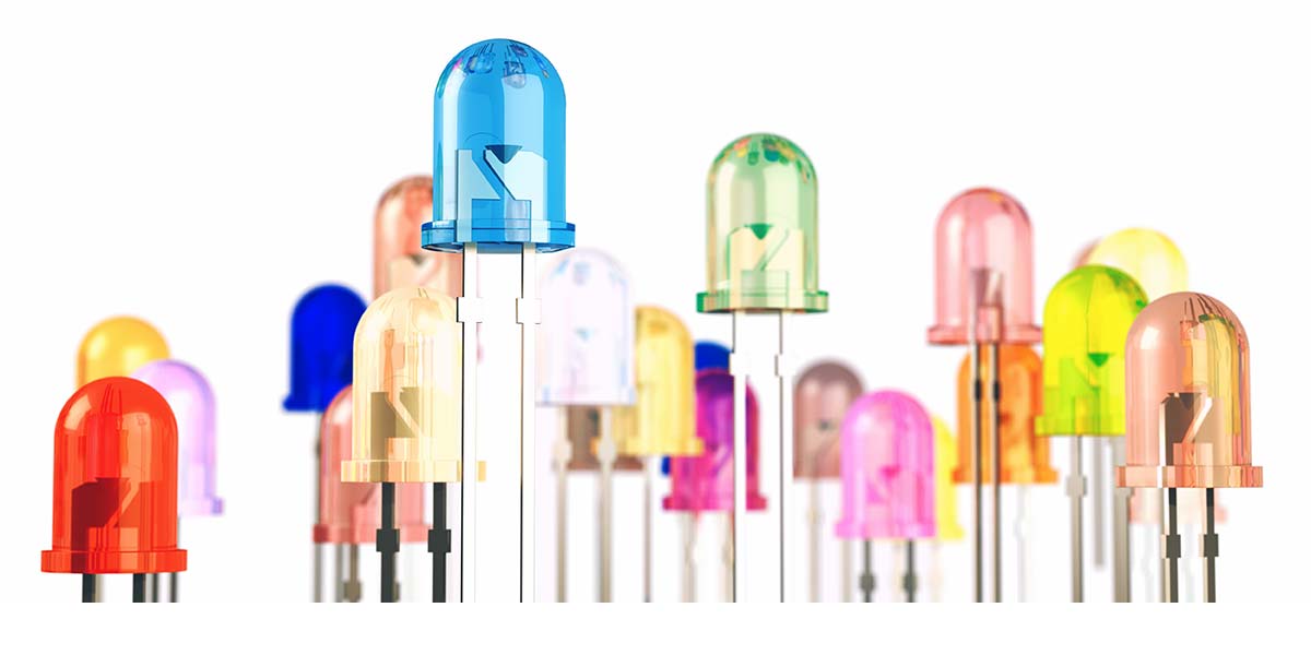
There’s also the practical side of things to consider. If there are a lot of inputs, outputs, and decisions made by your circuit, then having everything displayed on the front of your project box will make things cluttered and may even present a bit of “information overload.” I think some combination of the two ideas mentioned would be in order. Fortunately, there are plenty of options to fill both needs as shown in Photo 1.
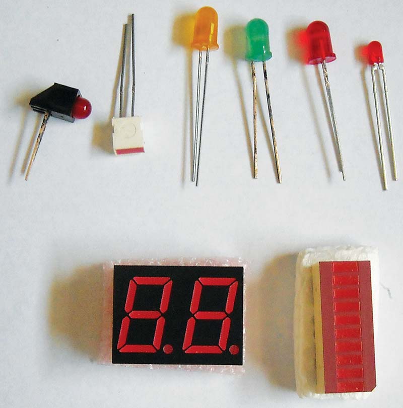
PHOTO 1.
The top row (L-R) shows a 90˚ circuit-mount LED, typically used on the edge of a printed circuit board (PCB) when the PCB is mounted in such a way that the edge with the LED is near the front panel of an enclosure (or on a card used in racks); a rectangular LED; and typical “bullet” shaped LEDs most commonly used on both circuit boards and front panels.
The second row shows (L-R) a two-digit seven-segment display (which are either common cathode or common anode; refer to Figures 2 and 3) and a 10-segment bar graph LED. While more types exist, the ones shown here are the most common and often used.
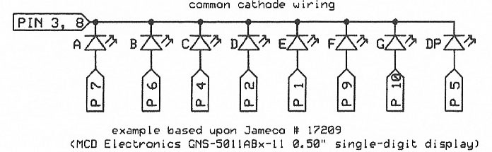
FIGURE 2.
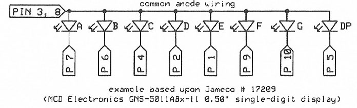
FIGURE 3.
Since pinouts of the seven-segment display can vary by manufacturer, the segment on the front of the display is referenced by letter (see Figure 4) to make drawings on schematics more universal; actual assembly pinouts are provided in the datasheets of the displays; again see Figures 2 and 3.
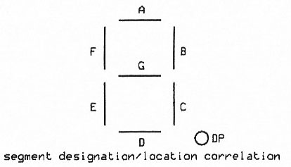
FIGURE 4.
Conclusion
CMOS ICs have been utilized to allow for operation at +12V — the most commonly available voltage in ham shack and mobile environments. They also can be operated at +5V, should we want to apply these principles to TTL circuits. Resistor values have not been specified for this reason, as well as to allow for variations of the LEDs used (2V, 20 mA versions may be the most common, but check your datasheets first!).
Also — especially when using a good number of LEDs — be sure to heatsink the power supply regulator (if running a separate supply for this circuitry) and/or when running multiple seven-segment displays at the full rating of 20 mA for each segment, since currents can easily be several hundred milliamperes. NV
Notes for Figures 1-4 and Schematics 1A and 1B:
- Figure 1 shows the basic nomenclature of an LED, regardless if it’s a single unit or part of a multi-LED display. In a single LED round package, the anode has the longer of the two leads and is always the more positive of the two leads.
- Multi-segment displays (seven-segment is the most commonly used) are typically designated as either “common cathode” or “common anode” (see Figures 2 and 3).
- Figure 4 shows the seven-segment display LED assignments (letter corresponds to the LEDs shown in Figures 2 and 3). Package size varies depending on the physical size of the LED (10-18 per package size); Jameco P/N 17209 (MCD Electronics P/N GNS-5011ABx-11 [0.50” single digit display] used here for an example).
- Current-limiting/voltage drop resistor required for all LEDs; omitted here for clarity.
Notes for Schematics 2 and 3:
- Seven-segment displays may not fit into standard IC sockets, depending on size (width, not just length).
- Resistance values will vary on not only supply voltages chosen, but by LED specifications as well.
- U1 and U2 can be chained together for multi-number displays (single number display shown for clarity).
“RTTY Detector,” CQ: Amateur Radio Magazine, September 2018, pages 32-6.
“Microphone PTT Time-Out Timer,” CQ: Amateur Radio Magazine, January 2019, pages 55-8.