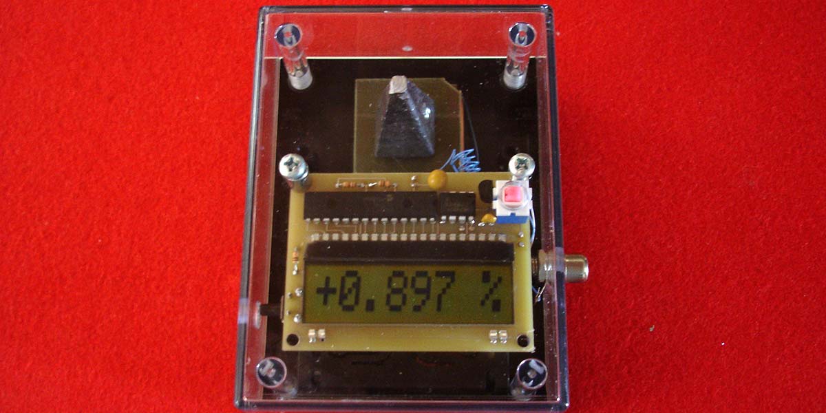
Gravity is that mysterious force that most of us fight when we step on the scales. Actually, it's not our weight we need to worry about, but our mass. If it wasn't for Isaac Newton, we would all be floating around space as he discovered gravity. Some people believe that the pyramids were built by aliens using an anti-gravity technique. So, the weight for this project is in the shape of a pyramid. Its name may be a little tongue in cheek, however, this is a very serious working instrument.
This project is easy to construct because it has no surface-mount components. It uses an inexpensive LCD display that does graphics and alpha numeric characters which are all driven by 11 inputs.
With the discovery of the God particle, it probably puts us closer to possible proof that graviton particles exists. Gravity is different in areas of the Earth for several reasons. On high mountains, you weigh less due to being farther from the mass of the planet. At the equator, centrifugal force plays a part, versus measurements at the north and south poles. A one ton object weighs seven pounds less at the north pole than at the equator. I think you'll be amazed at the number of variations you will see in gravity with this novel device.
Super novas and black holes also affect the Earth’s gravity. Plus, it has been reported that gravity changed from 1% deviation to 2% deviation in the 1980s. The Gravimeter can be used to measure these different phenomenon, and it also has practical applications in the discovery of large deposits of oil and minerals (since their masses differ). Oil is often found under salt domes which have less mass than that of iron. So, if you're looking for buried treasure, here is another gadget for your tool box.
Commercial gravimeters can be very expensive. They often employ a pendulum method which was used by Henry Cavendish in the late 1800s. Balance scale gravimeters use a spring and a weight.
I tried several types of sensors and decided on using a very simple one that detects the change of resistance by a weight using conductive foam. This is equivalent to a spring type of scale gravimeter. It has the advantage of being more rugged since there is no spring bouncing up and down. However, it has the disadvantage of time because the foam will age and lose its elasticity.
Multipurpose Board
Studying the ASM code (included in the downloads) of the PIC16F916 we'll be using will give you an idea of how to program the display for other projects. I have included programming pads for the use of a Microchip PIC 2 programmer.
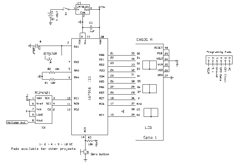
Gravimeter schematic.
As suggested, the board can be used for other projects such as measuring resistance, capacitance, and voltage, or for counting “events” by changing the code. Extra pads have been added for those who wish to use the display board for other purposes.
Electronics
The sensor is a variable resistor comprised of electro-conductive foam. It changes resistances when squeezed together. It has a resistance of approximately 1,000 ohms when constructed. The PIC uses a process for calculating the time it takes the resistor to charge a capacitor.
The formula for charging a capacitor is R * C = t. R is in ohms and C is in farads; “t” is in seconds.
1,000 * 100 µF = .1 seconds
The TMR0 register is used as it advances one count every .000, 001 of a second. When it rolls over to 255, it causes an interrupt and increments two more registers until the voltage exceeds a preset amount in the comparator. So, 1,000,000 per second x .1 seconds = 100,000 counts. Since gravity can vary ±2%, the count can vary by 2,000 counts.
There are a number of algorithms built into the software which perform addition, subtraction, multiplication, and division.
Once a base count is established, the difference in counts between the base count and the new count is determined. This difference is then divided by the base count times 100. This will give a percent change of the gravity field. (Refer to the equation below.)

The microprocessor used has memory areas to store previous data. When pressing the zero switch, this “zeros” the base count number and stores it in the EEPROM area. Pushing the zero button while pressing the on/off switch will load the base count. If it’s not pushed, it will calculate a new base count after averaging 25 counts.
The Detector
Cut two 1.25” square single-sided copper boards. Solder two 4” wire-wrap wires to each plate. Cut the wire off of the bottom of the 2 oz pyramid sinker; sand flush and glue it to the top pad on the non-conductive side.
Do not use steel weights because they are subject to magnetic fields.
Using double-sided tape, press the other copper board face up to the bottom of the chassis center, about 1/8” from the side opposite the battery compartment. The wire should be facing the battery compartment.
Cut a 1” square of conductive 1/4” foam (the stuff that electronic parts are often shipped in). Put a small drop of graphite-filled conductive wire glue (RadioShack #64-146) on the bottom corners (1 and 3) of the conductive foam and place this on the bottom copper board.
Add a drop of glue on corners 2 and 4 on the top side of the foam, and center the other board. Allow this to dry overnight.
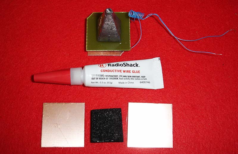
Sensor components.
Do not use too much glue as it will flow through the foam and short it out. You must use conductive glue. Treat the sensor gently because the foam can tear from the boards. The sinker will help hold the sensor while it sets.
After it’s dry — using an ohmmeter — check the resistance of the two plates; it should be around 500 to 1,000 ohms.
Component Specifics
The unit is powered by a nine volt battery. IC3 is an LM7805 five volt voltage regulator. The circuit draws 3.5 mA, and the battery should last about six days.
C1 smoothes out any ripples. If you're going to leave it on all the time, use a nine volt battery eliminator.
The PIC shorts out the charging capacitor C2 and then voltage is applied across the sensor. The capacitor will charge and when its voltage reaches a preset value of the comparator, it signals the microprocessor to calculate the number of counts the TRM0 register has made during this charging period.
The math functions take over from there. The display shows up to three decimal places. The DAC is a 12-bit digital-to-analog converter. Its voltage is centered at 2.5 volts for a zero position on chart recorders. The ± percent change is added or subtracted from 2.5 volts.
This gives a very sensitive graph. My first recording went off the chart, so I reduced the chart reading by two (∴ ± one volt from 2.5 volts = 2% gravity change).
The Chassis
The first thing to do is put the box together with screws as they have to form threads. This will make it easier to assemble when you put everything together.
Get the chassis templates from the downloads. Cut the template and glue it on the top of the box. Drill the five holes as called for on the drawing. The templates can be removed with hot water.
Place the jack from the left outside of the box and secure it with its nut.
The Circuit Board
The circuit board files are generated using ExpressPCB and are also included in the downloads, along with Hints and Tips, a source list, and ASM files.
Use a 6-32 tap and tap the two corner holes. Solder R1, R2, R3, and C1. Note the polarity of C2 and solder the positive terminal to the square pad.
Solder IC1 and IC2, noting pin 1 goes to the square pads. Solder IC3 with its flat side pointing towards the edge of the switch. Solder in opto 1. Solder the on/off switch. Turn over the board and solder the momentary switch to the bottom side.
The chip can be programmed using the five program pads under the LCD. Use a PIC 2 or PIC 3 programmer. The assembly file is in the downloads.

Top of the board.

Bottom of the board.
Use two different 4” colored wire-wrap wires to the pads next to pin 7 and pin 8 of the DAC. The wire from pin 8 goes to the center post of the RCA jack, and pin 7 goes to ground. Pass the two wires from the nine volt battery holder through a hole in the battery compartment, then through the strain hole. Solder the red wire to the + terminal and black to the - pad. Solder the two wires coming from the detector to the “in” pads. They have no polarity.
Place two 1” 6-32 screws in the two holes from the top side of the chassis. Turn it over and add the 3/8” standoff to the screw opposite the switch. Screw the board to the top of the chassis. The tapped holes will act as nuts. When finished, add a drop of finger nail polish to the ends of the screws to prevent them from turning.
Using the Unit
Add a nine volt battery. If using data logging software, plug the data acquisition module into the jack.
Place the unit on a flat, level surface and push the on switch. The unit will display “LOADING.” Push the zero button; the display should change and display “STANDBY.”
After about 30 seconds, the display will change to “STORING” and then display the percentage.
You can zero the instrument any time by pushing the zero button on the side. It will store the base readings in the EEPROM.
Keep in mind that the unit will be subject to temperature change and probably barometric pressure due to the foam bubbles. (It also makes a good seismic detector.)
Always remember, to determine the gravity of any situation, you must weigh all the facts. NV
A limited number of kits are available at the Nuts & Volts Webstore.
| ITEM |
QTY |
DESCRIPTION |
PT# |
SOURCE |
| C1 |
1 |
.1 µF 50 volt |
|
|
| BH |
1 |
Heavy duty 9V snap connector |
|
|
| BOX |
1 |
4.38 x 3.25 x 2.00 9V (black) |
SR232-CB |
Serpac |
| IC1 |
1 |
Microprocessor |
PIC16F916-I/SP |
Microchip |
| IC2 |
1 |
DAC 12-bit |
MCP4921-E/P |
Microchip |
| IC3 |
1 |
Five volt regulator 7805 |
|
|
| J1 |
1 |
RCA phone jack |
|
|
| OPTO 1 |
1 |
LCD display |
EADOGM081L-A |
Electronic Assembly |
| R1-R3 |
3 |
10K 1/6 watt |
|
|
| S1 |
1 |
Switch push DPST |
PVA1 EE H1 |
C&K |
| S2 |
1 |
Momentary SPST rt angle |
EVQ-PF0008K |
Panasonic |
| HARDWARE |
|
|
|
|
| CONDUCTIVE FOAM |
1 |
1/4" x 1" x 1" |
|
|
| CONDUCTIVE GLUE |
|
|
#64-146 |
RadioShack |
| LEAD WEIGHT |
1 |
2 oz sinker pyramid |
|
|
| SCREW |
2 |
6-32 1" |
|
|
| STAND-OFF |
1 |
#6 3/8" |
|
|
| WIRE-WRAP WIRE |
|
Two colors |
|
|
| NINE VOLT BATTERY |
|
|
|
|
Downloads
Parts, Template, .ASM file, .PCB file, .SCH file, and Hints/Tips Document.