You can buy inexpensive PS-2 keyboards, but they don't produce ASCII values many applications need. To further complicate things, these keyboards have their own code-transmission protocol. I'll show you how to use a system-on-a-chip and a bit of software to convert PS-2 key codes to corresponding ASCII values.
The PS-2 keyboard engineers assigned a unique code to each key. So, for example, the W key produces 0x1D and the X key produces 0x22 (all values given in hexadecimal). These codes don’t directly translate into ASCII values; 0x57 and 0x58, respectively. A PS-2 keyboard does, however, transmit key codes in a UART-type format: a start bit; eight data bits; an odd-parity bit; and a stop bit (Figure 1). The least-significant bit (LSB) of a key code gets shifted out first.
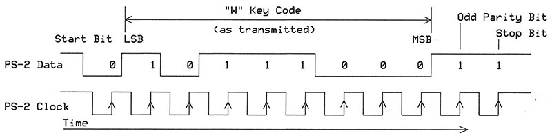
FIGURE 1. A PS-2 keyboard transmits data and clock signals when I press the W key, which has the assigned code 0x1D (MSB first).
You might think a UART could handle this serial information, but keyboard clock frequencies can vary between 10 kHz and about 16 kHz, so a UART set for a fixed bit rate might not work in all cases (Note 1). Many MCUs include a serial-peripheral interface (SPI) port that can operate as a slave device and receive serial data. In this mode, the keyboard can supply the needed serial data and clock signals. The MCU can then process the information and act accordingly.
NOTE 1. A person in a support group reported using a UART with a 12,000 bits per second (bps) clock. Worth a try, but an SPI port can better handle clock frequency changes from keyboard to keyboard. My PS-2 keyboard produced a clock signal equivalent to 13,700 bits/sec.
Connect a PS-2 Keyboard to an MCU
When you press the W key, the keyboard transmits the key code 0x1D. When you release the W key, the keyboard sends a key-release code, 0xF0, followed by the W key’s code, 0x1D (Figure 2). The key-release code remains the same (0xF0) for all keys.
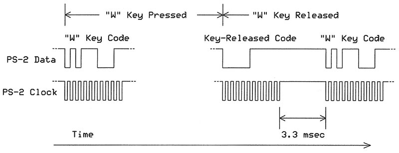
FIGURE 2. The serial transmission when I press and release the W key. Upon release, the keyboard transmits the key release code, followed by the W key code.
This article covers the keys in the large main alphanumeric keyboard area. It does not discuss auxiliary keys such as Home, Page Up, and Page Down, but you may easily modify the software to include them if you wish.
Use a System-on-a-Chip (SoC)
For this project, I chose a Cypress Semiconductor CY8CKIT-059 5LP prototyping kit (Figure 3) and the free Cypress PSoC™ Creator software you can download and install on a host PC. Cypress sells the prototype kit for $10. The board connects to a PC via a USB cable.
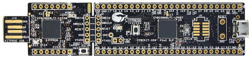
FIGURE 3. A CY8CKIT-059 5LP prototyping kit. The four contacts on the left mate with a female USB connector. These signals communicate data and programs between the PSoC chip and your host PC. Photo courtesy of Cypress Semiconductor Corp.
Print the documents, “PSoC 5LP Prototyping Kit Guide” and Cypress AN77759 “Getting Started with PSoC 5LP,” and use them to get off to a quick and easy start. (Directions are included with the article downloads.)
A Cypress 5LP PSoC (Programmable System-on-a-Chip) device includes many “building blocks” for functions such as SPI, USB, and UART ports; EEPROM; clocks; analog-to-digital converters (ADC); pulse-width modulators (PWM); and so on.
Unlike other MCUs, the 5LP devices only implement (or “connect”) the blocks you want. You select a function, drag its block into the PSoC Creator schematic drawing area, and set parameters.
In most cases, you don’t need to set bits in registers. Each block has its own datasheet, and example programs give you a head start. When you “build” a project, the PSoC creates the APIs for you. The documentation for each block lists the APIs and explains their uses.
Configure an SPI Port for 11 Bits
Figure 4 shows an SPI slave port as I configured it. The MOSI (master-out, slave-in) pin connects to the keyboard’s data-output signal. The keyboard clock connects to the SPI serial-clock input (sclk). I connected the slave-select input (ss) internally to a logic 0, so the SPI block stays active at all times.
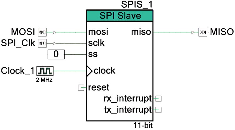
FIGURE 4. My SPI port in the PSoC Creator schematic window. You drag and drop an SPI and other building blocks into the schematic area as needed and connect them with "wires." Later, you assign signals to physical I/O pins. I used the default name SPIS_1 for this block, but you can change it as you wish.
Like many other PSoC components, the SPI port requires an internal synchronizing clock. I chose a clock from the list of blocks and set it for a 1 MHz output. The documents mentioned earlier explain how to start a project like this, configure blocks, assign physical I/O pins to signals, and build a project with the PSoC Creator software. (I connected the MOSI to a PSoC output pin, but this project does not use it.)
A rapid double-click on the SPI slave block opens the SPIS_1 Configure window shown in Figure 5. Here, you select one of four modes, and as you examine each, the timing diagram changes to illustrate the signals for that mode. I chose the clock-phase (CPHA = 1) and the clock polarity (CPOL = 1) that match the keyboard clock and data signal levels and edges shown earlier (refer back to Figure 1).
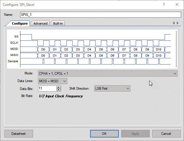
FIGURE 5. This SPI_Slave Configure window appears after a double-click on the SPI function shown in Figure 4. You may choose the type of signals for the SPI port, the number of data bits, and whether the MSB or LSB shifts in first.
The PSoC SPI block works with from three to as many as 16 bits. I chose 11 bits to match the number of bits transmitted by a keyboard. I also chose LSB first as the shift direction for incoming data to match the keyboard’s data format. This setting simplifies software for keyboard decoding.
The Advanced section of this window (Figure 6) lets me select an external clock: the 1 MHz clock shown in Figure 4. This clock signal is external to the SPI block and used only within the PSoC to synchronize processor and logic activities. I also chose an SPI buffer memory size for four 11-bit values, and no interrupts. Anyone familiar with peripheral setup in a typical MCU will appreciate the ease of SPI setup.
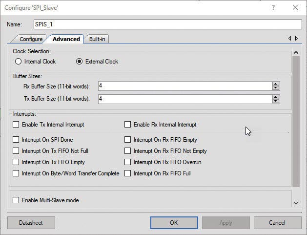
FIGURE 6. The SPI advanced configuration window lets you set the SPI buffer memory size, choose a clock, and set interrupts if any. The clock refers to a PSoC internal synchronizing clock, not the clock signal from a PS-2 keyboard.
That simplicity applies to other blocks, too. You don’t search through lists of registers to find a bit that enables a peripheral and then tinker with other bits to get the behavior you want. The PSoC Creator handles those details. The software does the same things for a UART in this project. The UART sends ASCII values to a terminal emulator on my PC.
A separate window lets you assign the signals to physical I/O pins. In this project, the keyboard’s data output connects to port 3, bit 0 (noted as P3.0) and the keyboard clock signal connects to port 3, bit 1 (P3.1). A UART output connects to port 12, bit 7 (P12.7), which routes the signal to another MCU on the small programmer section of the prototyping board.
This MCU communicates with a host PC via the male programming USB connector. I chose the Parallax Serial Terminal (PST) software for debugging and testing.
A PS-2 keyboard has four connections with a computer: two wires for +5V and ground; and two wires to transmit a serial key code and a synchronizing clock signal (Figure 7).
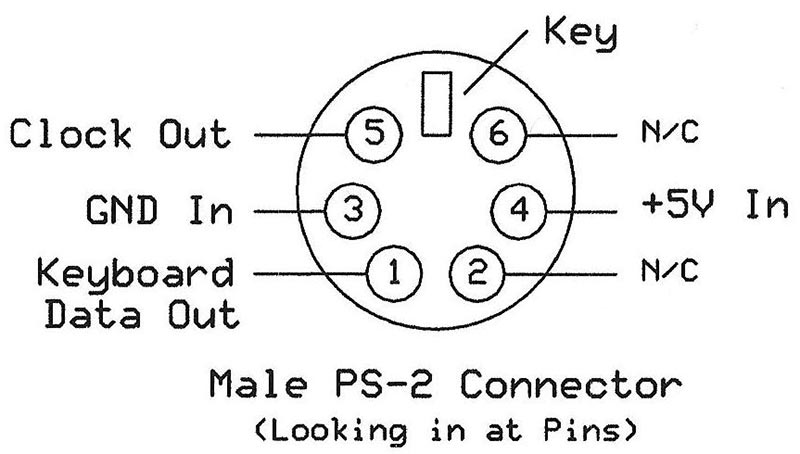
FIGURE 7. The pin connections for a PS-2 keyboard. (Viewed looking into the male pins.)
This view looks into the pin (male) end of a PS-2 keyboard connector, or at the solder contacts on a mating female connector. The PSoC 5LP Prototyping Kit Guide includes a table of pin names, signals, and descriptions for the PSoC board. Table 1 lists the keyboard-to-prototyping kit connections you need for this project.
| Keyboard Signals |
PSoC Signals |
| Name |
Connector Pin |
Name |
Signal |
Pin Name |
| +5V In |
4 |
VDD |
+5V Power |
J2_01 |
| GND In |
3 |
GND |
Ground |
J2_02 |
| Clock Out |
5 |
P3.1 |
GPIO |
J2_24 |
| Keyboard Data Out |
1 |
P3.0 |
GPIO |
J2_25 |
TABLE 1. Keyboard and PSoC Prototyping Kit Connections.
Software Builds the Project and Creates the Files
When the PSoC Creator “builds” a project, it creates and uses many files which at first can seem overwhelming. Figure 8 shows a portion of the Workspace Explorer area on the left side of the PSoC Creator window. Because this project does not use interrupts, all my software went into the main.c file. Before I wrote any code, I had to decide how to process the keyboard data and how to handle the key release code and the shift keys.
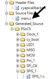
FIGURE 8. Don't let the list of PSoC files and folders intimidate you. You'll only work with the main.c file unless you use an SPI interrupt, which would add only one other file for an ISR.
Every Key has Its Code
Because every key has a unique code, you might try to use that code as an index into an array of ASCII values; basically, a lookup table. That’s a good idea. You could create the array ASCII_Equivalent[ ] in which to store the ASCII values. Then, the W key code 0x1D, for example, would direct software to array element ASCII_Equivalent[0x1D] that would hold the W key’s ASCII code. So, do we save the value for an uppercase or lowercase W in the array? It depends. The software must monitor codes from the two shift keys (one on the left and one on the right of the keyboard) and decide which ASCII value to retrieve. So, we create two arrays — LC_Array[ ] and UC_Array[ ] — for lowercase and uppercase ASCII values.
Table 2 shows part of the information for each array. The downloads for this article include the complete table, and the PSoC software includes both arrays and all PSoC files. Gray rows in the table indicate an unused code or no value assigned for a key such as F1 or F2.
| PS-2 Keyboard Scan Code |
Lower-Case Characters |
Upper-Case Characters |
| Decimal |
Hex |
LC Keyboard Char |
LC ASCII Value |
UC Keyboard Char |
UC ASCII Value |
| 20 |
14 |
c |
63 |
C |
43 |
| 21 |
15 |
q |
71 |
Q |
51 |
| 22 |
16 |
1 |
31 |
! |
21 |
| 23 |
17 |
|
0 |
|
0 |
| 24 |
18 |
|
0 |
|
0 |
| 25 |
19 |
|
0 |
|
0 |
| 26 |
1A |
z |
7A |
Z |
5A |
| 27 |
1B |
s |
73 |
S |
53 |
| 28 |
1C |
a |
61 |
A |
41 |
| 29 |
1D |
w |
77 |
W |
57 |
TABLE 2. A portion of the lowercase and uppercase information for PS-2 keyboard-to-ASCII conversions. The keyboard does not assign codes 0x17 through 0x19 to any keys.
A Flowchart Maps Our Way
The translation of key codes into ASCII values gets more involved as shown in the software flowchart (Figure 9). This code runs in an infinite loop, but you could use it as the basis for an interrupt-service routine (ISR). That approach goes beyond the scope of this article.
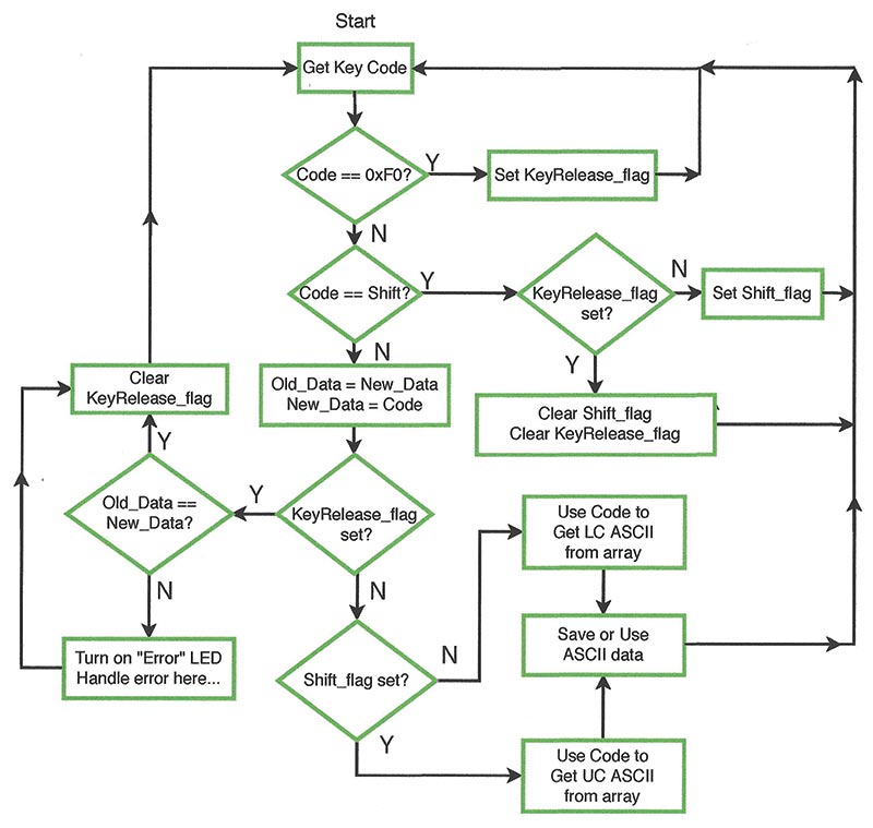
FIGURE 9. Flowchart for the PS-2 keyboard code converter that produces corresponding ASCII values for shifted and unshifted keys.
The keyboard software has three main tasks. First, it waits for the SPI buffer memory to become “not empty,” which signals new information has arrived in the SPI port. Second, the software must properly detect the shift key’s condition to choose an uppercase or lowercase ASCII value. Third, it must handle the key release code and the key code that follows it to ensure we don’t get duplicate characters when we release a key.
The software uses two true-false flags: KeyRelease_flag, which when true indicates the software has detected the 0xF0 key release code; and Shift_flag that gets set to true when the software senses a pressed shift key (but not caps lock). Please refer to Figure 9 as I explain the software operations. Suppose I press the letter G. The “Get Key Code” software section converts the 11-bit keyboard information into the eight-bit keyboard code (Keyboard_Data in the software). This keyboard value equals the G key code, 0x34.
The next software section tests the value to determine if it equals the key-release code, 0xF0, or either shift key code, 0x12 or 0x59. In this case, the G key value matches none of these three conditions. So, the program continues and the value from some previously pressed key goes into variable Old_Data; the G key value, 0x34, gets put into the New_Data variable.
This process lets the software later determine if the key just released has the same code as the key pressed earlier. It’s simply a way to detect an error, such as pressing two keys at once. More about this shortly.
Next, the software tests the KeyRelease_flag, but because I haven’t released the G key this flag is false. Then, based on the state of the Shift_ flag, the MCU decides whether to fetch the ASCII value for the uppercase UC_Array[ ] or from the lowercase LC_Array[ ]. I haven’t touched a shift key, so the Shift_flag is false, and the software gets the lowercase g ASCII value 0x67. The software then goes back to await arrival of a new key code. (In my software, the ASCII value goes to my host PC and the terminal displays “g.”)
When I release the G key, the software must recognize the key release code and then ignore the key code that closely follows (refer back to Figure 2). Without this test, the software would sense two key codes from the pressed and released key, and a terminal would display “gg.” Here’s how the software avoids the “double g” problem.
Detect a Key Release
When I release the G key, the keyboard transmits the key release code, 0xF0, which the software detects and then sets the KeyRelease_flag to true. Next, the program goes back to wait for another value from the SPI port. In this key release example, the keyboard again sends the value for the G key (0x34).
The program compares the final G key data with 0xF0 and with both shift key values. Again, the G key code doesn’t match these values, so the software goes on to transfer the New_Data value (the G key data sent when I pressed the G key) to Old_Data. The second G key value — sent after the key release code — gets saved in New_Data. Thus, we have:
- Old_Data = 0x34, G key code sent when key pressed
- New_Data = 0x34, G key code sent when key released
The software now “sees” the KeyRelease_flag as true, so it compares Old_Data and New_Data. When they match, all is well, and the software clears the KeyRelease_flag and loops back to handle the code from the next key I press.
In this way, the software properly ignores the G key code sent right after the key release code. Plus, we don’t see “gg” on a terminal; only “g.” If the Old_Data and New_Data values do not match, a command turns on an “error” LED on the PSoC board. You may add error-handling software if you wish.
Shift Happens
The two shift keys operate the same way as other keys. Each sends its code when pressed and sends the key release code and its shift key code again when released. The flowchart in Figure 9 shows how the shift key affects the choice of ASCII value.
When I press the left shift key, the software receives 0x12 and tests it for a match with the key release code (no match) and the code for each shift key. The software detects a match with one of the two shift key codes and branches to test the KeyRelease_flag. If this flag is false, the software sets the Shift_flag and goes back to get the next code from the SPI port.
As long as I press the shift key, the Shift_flag remains set and the software selects ASCII values from the uppercase UC_ASCII array. When I release the shift key, it produces the key release code (0xF0) and that condition causes the software to set the KeyRelease_flag.
When the SPI port receives the shift key code that follows the release of a shift key, the software tests the KeyRelease_flag. If it detects a set KeyRelease_flag, it clears the KeyRelease_flag and the Shift_flag. (The software does not use the caps lock key, 0x58, which I despise and have removed from my keyboards because I hit it by accident too often.)
Time to Get Started
The article downloads contain all the software and files needed for this project. If you choose to use a different processor, I have included the C language code in a separate text file. I leave it to you to set up and create code for your MCU’s SPI port. The PSoC project also contains the C program in main.c. There’s a Get Started guide (PDF format) that explains how to open this project in the PSoC Creator software. You can then examine the “innards” of the project.
A second version (Bundle04) of the software is available to handle key rollover. The first version works but it doesn't handle this; that is, several keys pressed at the same time. The second version does. Key rollover isn't a problem for most typists, but it happens once in a while, so people may use the second version if they wish. I hope this information will be “key” to your success! NV
Resources
Cypress PSoC Creator 4.2
https://www.infineon.com/cms/en/design-support/tools/sdk/psoc-software/
Parallax Serial Terminal download (free)
https://www.parallax.com/downloads/parallax-serial-terminal
Bit-swap code is available at:
https://stackoverflow.com/questions/2602823/in-c-c-whats-the-simplest-way-to-reverse-the-order-of-bits-in-a-byte
Downloads
What’s in the zip?
Workspace Bundle 03-04
Keyboard Codes
Flowchart
Getting Started