Christmas season is my favorite time of year. I’ve built LED Christmas trees before from kits and original designs as Christmas gifts for my relatives and friends. This year, they’re due for an update.
General Description
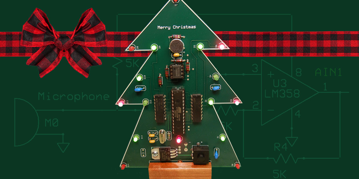
As shown in Figure 1, the LED Christmas Tree consists of a green printed circuit board in the outline shape of a tree decorated with 16 LEDs.
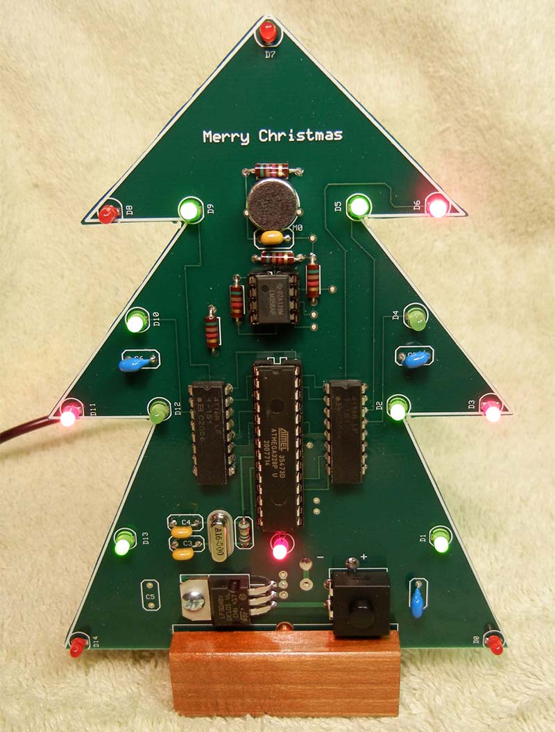
Figure 1. Finished Christmas tree.
A microphone responds to ambient sound to effectively clock a microcontroller (MCU) executing different LED sequence patterns. The unit is powered by a 6 VDC, 600 mA AC adapter (wall wart). Overall, it measures 6”H x 4”W x 2”D.
Features
- An Electret microphone connects to the MCU analog comparator pins (AIN0/AIN1) to detect sound which animates the LEDs.
- A 16-bit Linear Feedback Shift Register (LFSR) creates a maximal length Pseudo Random Bit Stream (PRBS) dynamic LED sequence. This produces a pleasing, eye-catching pattern as the bits shift in order around the 16 LEDs.
- If no sound is detected for 30 seconds, all the LEDs turn off and the tree enters a low-power stealth mode, fading discreetly into the background but poised to respond to the next sonic vibration.
- All through-hole component technology makes for easy assembly. Socketed integrated circuits enable firmware updates for user customization. Total cost is $40-60 each depending on quantity.
Hardware
Arduino provides a low-cost development environment that I have used before. The Arduino Uno ATmega328P MCU is certainly capable of driving 16 LEDs and interfacing with a microphone.
An Arduino Uno and a breadboard was everything required to develop this standalone ATmega328P project.
The Christmas tree printed circuit board is a four-layer board developed using ExpressPCB Classic free CAD tools. The top silk screen layer outlines the tree profile. A band saw cuts the final shape.
Microphone Interface
An Electret microphone is very sensitive but its output signal needs amplification. There exist fine (and cheap) microphone amplifier modules that produce nice analog waveforms (e.g., based on MAX4466). For aesthetic reasons, I needed something much simpler and using minimum through-hole components.
Here, the microphone output is capacitively coupled to an LM358 operational amplifier. The voltage gain of the amplifier is 2x, so it really behaves more as an impedance transformer.
This signal is enough to trip the MCU analog comparator inputs AIN0,AIN1. The circuit is shown in Figure 2.
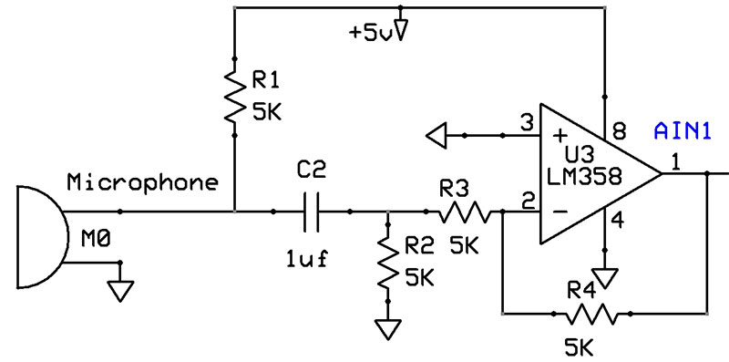
Figure 2. Electret microphone interface circuit.
It should be noted that in order see the on/off contrast of the switching LEDs, the rate of switching must be less than about 25 per second (40 msec period). This is about the frame rate of old motion picture films.
While the ATmega328P is capable of capturing sound at much higher frequencies, the LEDs won’t appear to dance with the beat.
Firmware Sketch
This sketch is short and very simple, only 1900 bytes are flashed (about 4% of available program and variable space). All the LED dynamics are driven by two Interrupt Service Routines (analog comparator and Timer1). Take a look at Figure 3.
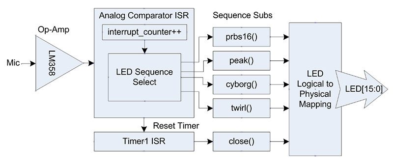
Figure 3. Software functional block diagram.
Each time an analog interrupt occurs, an interrupt counter is incremented. This value, depending on the range, decides which sequence subroutine to execute.
The sequence subroutine operates like a finite state machine where each call advances the sequence by one clock tick. The LFSR sequence is generated algorithmically but other patterns are defined by a multi-dimensional array.
The first dimension defines the sequence step while the second dimension lists the LEDs to turn off and on. A multi-dimensional array allows the programmer to create any LED sequence in a straightforward manner, limited only by your imagination and MCU memory size.
Timer1 is the MCU’s only 16-bit timer (max value is 65535 counts). When a timeout occurs, all the LEDs are turned off. In order to achieve a 30 second timeout delay, the CPU clock is divided by 16 making the internal CPU clock frequency 1 MHz.
To avoid premature timeout, Timer1 is reset every time an analog comparator interrupt occurs.
The sketch includes five canned LED sequences and debug compile options for using the Arduino serial monitor. Many debug problems required stand-alone, real-time operation without the serial monitor.
Linear Feedback Shift Register (LFSR)
Please see the sidebar for a general discussion of LFSRs.
Here, we’re creating a 16-bit LFSR with xnor’d feedback from Q1, Q2, Q4, and Q15 outputs to D0 input. This creates a maximal length PRBS of 65535 unique 16-bit combinations (2^16 – 1) where each register stage corresponds to an LED.
The pseudo random bits march through each of the 16 LEDs in order. As currently programmed, it takes over 40 hours to complete the full sequence. Implementing an LFSR algorithmically in software is very simple (see prbs16() C code below).:
char D[16], Q[16]; // global variables
void prbs16() {
for (byte i=0; i<16; i++) {Q[i] = D[i];}
// feedback
D[0]=xnor(xnor(Q[15],Q[4]),xnor(Q[2],Q[1]));
for (byte i=0; i<16-1; i++) {
D[i+1] = Q[i];
D[i] == '0'? digitalWrite(Qmap[i], HIGH):
digitalWrite(Qmap[i], LOW);
}
D[15] == '0'? digitalWrite(Qmap[15], HIGH):
digitalWrite(Qmap[15], LOW);
delayMicroseconds(LEDdly);
}
Assembly
To perform the stand-alone ATmega328P programming, I modified an Arduino Uno by replacing the 28-lead MCU DIP (Dual Inline Package) with a narrow 28-lead ZIF (Zero Insertion Force) socket. This enabled me to program an MCU unit in the normal Arduino Uno environment, then plug it into the Christmas tree socket.
I built the Adafruit 462 stand-alone AVR ISP Programmer Shield Kit to program bootloaders into raw MCU ICs.
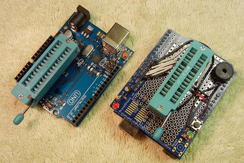
Figure 4. ATmega328P 28L DIP MCU programming tools.
Conclusion
This was a satisfying project because it created unique Christmas gifts for my relatives and friends. Children especially enjoy the voice/audio interaction. No doubt my relatives will not be satisfied unless my next revision is controlled by a smartphone app and automatically uploads data to Cloud storage for real time ambient noise analysis.
I kept one tree for myself to set on top of my piano, so I can entertain guests with a multi-media performance of Christmas carols.
Programmers are invited to play with LED sequences, switching delays, and adding digital filters or other functionality.
Building this stand-alone MCU project also extended my development skills in the Arduino environment. Ten tree units were assembled with 100% yield. NV
Linear Feedback Shift Register (LFSR)
A Linear Feedback Shift Register (LFSR) is a logic circuit often applied in cryptography, authentication, random number generation, logic testing, communications coding, decoding, error correction, and wireless networking. Some LFSRs are capable of generating a pseudo-random bit stream (or sequence) (PRBS) using recursive feedback. LFSRs are often implemented in hardware (e.g. FPGAs) where very fast execution is critical (e.g. radar, Global Positioning System).
There are two main LFSR configurations. In Fibonacci LFSRs, two or more Q outputs are Xor’d (logic exclusive OR) to generate feedback (externally) to the first input stage (D0). The other type, named after Evariste Galois, inserts Xor’d feedback (internally) between the D-flop stages.
By taping different output stages for feedback, we can create different sequences with different run lengths. With proper choice of feedback stages, we can create a maximal length sequence with a run length of 2^n -1 combinations.
Example: Four-bit LFSR
With feedback taps chosen from Q0, Q3, this Fibonacci four-bit LFSR generates a maximal length PRBS of 15 combinations (2^4 – 1).
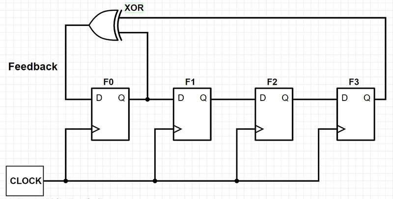
Figure A. Four-stage LFSR consisting of D-flops and XOR feedback.
| t |
D0 |
D1 |
D2 |
D3 |
Feedback |
| 0 |
1 |
1 |
1 |
1 |
0 |
| 1 |
0 |
1 |
1 |
1 |
1 |
| 2 |
1 |
0 |
1 |
1 |
0 |
| 3 |
0 |
1 |
0 |
1 |
1 |
| 4 |
1 |
0 |
1 |
0 |
1 |
| 5 |
1 |
1 |
0 |
1 |
0 |
| 6 |
0 |
0 |
1 |
1 |
1 |
| 7 |
0 |
0 |
1 |
1 |
1 |
| 8 |
1 |
0 |
0 |
1 |
0 |
| 9 |
0 |
1 |
0 |
0 |
0 |
| 10 |
0 |
0 |
1 |
0 |
0 |
| 11 |
0 |
0 |
0 |
1 |
1 |
| 12 |
1 |
0 |
0 |
0 |
1 |
| 13 |
1 |
1 |
0 |
0 |
1 |
| 14 |
1 |
1 |
1 |
0 |
1 |
| 15 |
1 |
1 |
1 |
1 |
Repeat |
| 16 |
0 |
1 |
1 |
1 |
Repeat |
Table 1. A maximal length four-bit LFSR state list.
If we count the number of consecutive 1s and 0s, we find that half are one-bit, one-quarter are two-bit, one-eightth are three-bit, etc.; up to 1/(2^n) are n bits wide. Thus, the distribution nearly equals the statistical expectation value for a truly random distribution.
This type of analysis is shown for our four-bit LFSR in Table 2. Some difference between Actual versus Ideal Probability Expectation is noted. However, for wider LFSRs, with more states these Expectation values are very close. This is what gives a PRBS its pseudo random quality.
width=
length= |
4
15 |
bits
combos |
Random Prob Expectation |
| Bit Pattern |
Run Length |
#Occur |
Actual |
Ideal |
| 'b1 |
1 |
2 |
0.25 |
0.25 |
| 'b11 |
2 |
1 |
0.125 |
0.125 |
| 'b111 |
3 |
1 |
0.125 |
0.0625 |
| 'b1111 |
4 |
0 |
0 |
0.0625 |
| 'b0 |
1 |
2 |
0.25 |
0.25 |
| 'b00 |
2 |
1 |
0.125 |
0.125 |
| 'b000 |
3 |
0 |
0 |
0.0625 |
| 'b0000 |
4 |
1 |
0.125 |
0.0625 |
Table 2. A four-bit LFSR statistical expectation.
Stream Cipher
Suppose we want to encrypt the message ‘HI’ which is ASCII capital ‘H’ (‘b0100 1000) and ASCII capital ‘I’ (‘b0100 1001). This makes our Plaintext = ‘b0100100001001001.
Select a 16-bit key from Table 1, e.g., column D0 from t = 2 to 16, i.e., key = ‘b1011001000111101. To encode the message, Xor each bit of Plaintext with the corresponding bit of K.
| Truth Table |
Xor |
Xnor |
| a |
b |
x |
x |
| 0 |
0 |
0 |
1 |
| 0 |
1 |
1 |
0 |
| 1 |
0 |
1 |
0 |
| 1 |
1 |
0 |
1 |
Encrypt (Encode)
Generate Ciphertext by Xor’ng Key with Plaintext
| t |
0 |
1 |
2 |
3 |
4 |
5 |
6 |
7 |
8 |
9 |
10 |
11 |
12 |
13 |
14 |
15 |
| Key |
1 |
0 |
1 |
1 |
0 |
0 |
1 |
0 |
0 |
0 |
1 |
1 |
1 |
1 |
0 |
1 |
| Plaintext |
0 |
1 |
0 |
0 |
1 |
0 |
0 |
0 |
0 |
1 |
0 |
0 |
1 |
0 |
0 |
1 |
| Ciphertext |
1 |
1 |
1 |
1 |
1 |
0 |
1 |
0 |
0 |
1 |
1 |
1 |
0 |
1 |
0 |
0 |
Decrypt (Decode)
Restore Plaintext by Xor’ng original Key with Ciphertext
| t |
0 |
1 |
2 |
3 |
4 |
5 |
6 |
7 |
8 |
9 |
10 |
11 |
12 |
13 |
14 |
15 |
| Key |
1 |
0 |
1 |
1 |
0 |
0 |
1 |
0 |
0 |
0 |
1 |
1 |
1 |
1 |
0 |
1 |
| Ciphertext |
1 |
1 |
1 |
1 |
1 |
0 |
1 |
0 |
0 |
1 |
1 |
1 |
0 |
1 |
0 |
0 |
| Plaintext |
0 |
1 |
0 |
0 |
1 |
0 |
0 |
0 |
0 |
1 |
0 |
0 |
1 |
0 |
0 |
1 |
Of course, this is a trivial example (so you can easily follow along). If the key (initial state) were much wider, say 256 bits, the number of possible keys would be 1E+77.
If you tried cracking the cipher by guessing 100 trillion keys per second, it would still take 2.5E+47 universe lifetimes to try every possible key. Chances of success are very low.
Parts List
| Qty |
Description |
Reference |
Digi-Key Part # |
| 4 |
10 µF Cap Ceramic |
C1 |
445-181284-1-ND |
| 1 |
1 µF Cap Ceramic |
C2 |
399-14024-1-ND |
| 8 |
Red LED |
D0 |
754-1725-ND |
| 8 |
Green LED |
D1 |
BL-BGE1V1-ND |
| 1 |
Microphone |
M0 |
102-1721-ND |
| 5 |
Resistor, 5K, 1/4W |
R1 |
RC14JT5K10CT-ND |
| 2 |
Resistor Array 150 ohm |
RA1 |
4116R-1-151LF-ND |
| 1 |
Switch On-Off |
SW1 |
CW181-ND |
| 1 |
Voltage Regulator +5V |
U1 |
497-14792-5-ND |
| 1 |
Dual Op-amp eight-pin |
U3 |
296-9554-5-ND |
| 1 |
ATmega328P 28L DIP |
U2 |
ATMEGA328P-PU-ND |
| 1 |
Socket 28L x 0.300 |
S1 |
ED3050-5-ND |
| 1 |
Socket 8L x 0.300 |
S2 |
609-4717-ND |
| 1 |
Crystal 16 MHz |
X0 |
887-2014-ND |
| 2 |
Capacitor 12 pF |
C3 |
445-173173-1-ND |
| 1 |
Resistor 1M, 1/4W |
R5 |
CF18JT1M00CT-ND |
| 1 |
AC-DC Adapter 6V, 0.6A |
|
|
| 1 |
#4-40 1/4" Screw & Nut |
|
|
| 1 |
Strain Relief Holder & Screw |
|
|
| 1 |
PCB (ExpressPCB) |
|
|
Downloads
What’s In The Zip?
Gerber Files
Datasheets
Parts Lists
Code
Worksheet
mp4 Video