The last 38 years of my career were spent in an industry where I designed and built test equipment. Early on, it was mostly discreet digital logic, then microprocessors, and finally microcontrollers. Some of the interface circuitry was analog, but mostly it was digital.
Now that I’ve retired, I’ve started experimenting with some of the analog subjects that I haven’t done much with since school back in the seventies. To begin with, I started with op-amp circuits; specifically, Colpitts oscillators. I built the circuit on one of those plug-in ‘protoboards,’ a ±15V power supply, an oscilloscope, and a multimeter.
One thing most of the textbooks and articles fail to mention is that a resistor is required in series with the Colpitts tank circuit, but only if you want it to actually oscillate. I built several different Colpitts oscillators using an NE5534A op-amp and fixed inductor, and capacitors. I found that oscillation could be achieved only for a certain range of the above-mentioned resistor, and that resistance range was different for each different combination of inductor and capacitors.
For my experimentation, I was using a trim pot. I would adjust until oscillation began, then power down, pull one end of the trim pot, measure the resistance, then re-connect, power up again, and continue adjusting until I reached the other end of the resistance range, where the oscillation would cease. I would then repeat the resistance measurement.
That procedure was not ideal. In addition to the multiple tedious steps, adjusting a trim pot can be a pain.
Fitting the tool over the little slotted shaft is awkward, and I always forget which way the resistance will go (increase or decrease), depending on the rotation direction. Sometimes, I would reach the rotational limit, and have to swap in a different trim pot.
As too often happens, the first project was put on hold while I pursued a new project, which is the subject of this article. Hence, this potentiometer box.
Yes, I could have purchased or built a decade resistor box, but I really wanted something that made smooth transitions like a potentiometer (as opposed to a decade box) which changes resistance in discrete steps. I want to see the oscilloscope waveform change smoothly with the resistance change. What I wanted was a set of potentiometers with real knobs, and with a way to measure resistance without having to go through all the steps I was doing with the trim pot.
I’ve been using the term ‘potentiometer’ a bit loosely here. A potentiometer has three terminals, with the center terminal being a wiper that moves between the other two terminals. Think of a voltage divider.
For my Colpitts circuit, what I am using is technically a ‘rheostat.’ Think of a potentiometer where only the wiper and one end of the potentiometer are connected. In other words, a variable resistor. My design offers all three terminals of each potentiometer. If you want a simple variable resistor, you’ll only use two of the terminals.
I decided on six dual gang potentiometers: 1K, 5K, 10K, 50K, 100K, and 1M. I dropped the 50K because it was not available in the same style as the others. Dual gang simply means two isolated pots driven by the same shaft. Let’s call them A and B.
This is not a project I wanted to spend a lot of money on. I had a plastic enclosure I wanted to use, and I had some leftover vector board strips, but not the potentiometers. Each potentiometer was $7 and some change, so I was already over $35 just for the five potentiometers. The big question, however, was what to do about the six hookup terminals needed for each dual potentiometer.
If you have deep pockets, you can find some nifty spring-loaded posts where you simply push down the top, stick a wire in the hole, and release, whereby the wire is nicely held in the post. You could also use banana plug receptacles and banana plugs. At three terminals for each half of five dual gang potentiometers, I need 30 terminals. Obviously, some low budget improvisation was required here.
Enter the paper clip: cheap and effective. With one bend and one cut (Figure 1), I get a nice little upside down ‘U’ shaped terminal, which can be inserted into and soldered onto a piece of vector board. Of course, these have to be the bare metal clips, not the rubber coated types. J-clips attach easily to the upside-down U clips, and it’s also easy to solder a wire onto these.
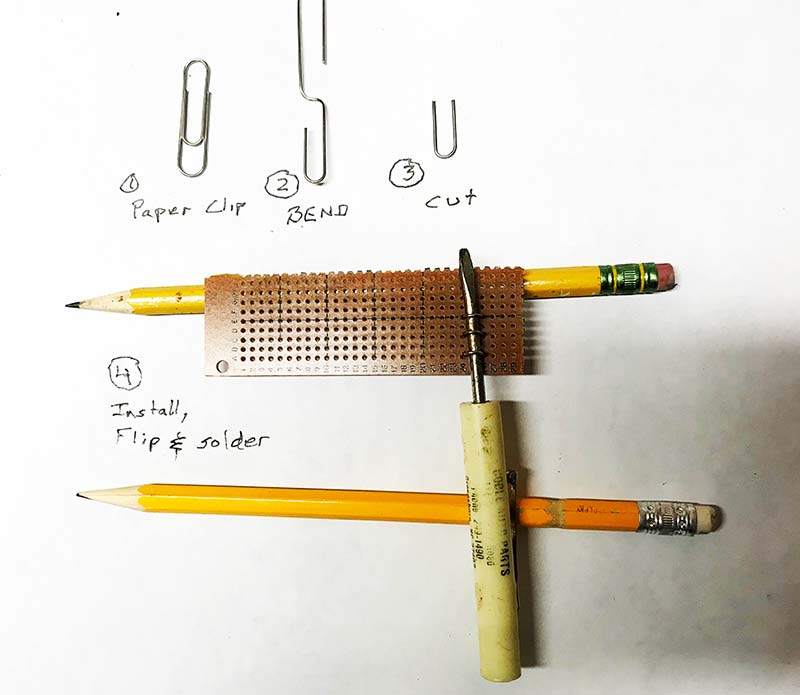
FIGURE 1. Paper clips are amazing items.
Why did I choose dual gang potentiometers? I had this fantasy where I could use one gang for my circuit and the other to be connected to an ohmmeter. That allows me to see the resistance in real time without having to kill power, disconnect a wire, and measure resistance. It would have been great. Problem is, it didn’t work very well because the reality is that the two gangs didn’t track very well.
For example, when I turn the 10K pot such that the A gang reads 5K, the B gang reads 4860. Back to the old drawing board.
Enter the single-pole double-throw toggle switch and another paper clip terminal for each gang. The wiper of a potentiometer connects to the center of the toggle switch. The other two terminals connect to the two clips associated with that potentiometer. Now, depending on the switch position, the wiper is either connected to the circuit clip or it’s connected to the isolated clip.
With your ohmmeter connected to one end of the rheostat and to the isolated clip, you can measure resistance by simply flipping the switch. Flip the switch to measure resistance, then flip it back into the circuit. Not as convenient as my original plan, but still a lot easier than the way I was doing it with the trim pot. (The switch is used only for rheostat applications, not for potentiometer, because the wiper has to be isolated from the circuit in order to make resistance measurements).
Because I had already purchased the dual gang pots, I decided to use both. Maybe I’ll find a use for that arrangement someday. If you decide to build this project, you can save time and money by using only single gang potentiometers.
The schematic is shown in Figure 2, along with some connection examples.
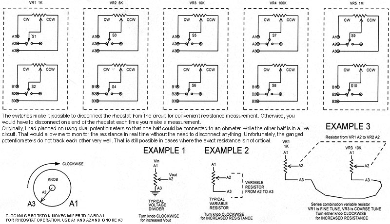
FIGURE 2. Schematic of the potentiometer box.
The wiring was carefully coordinated with two of my requirements. First, that clockwise rotation of the knob would result in an INCREASE in resistance when using the pot as a variable resistor (a rheostat). Second, that clockwise rotation of the knob would result in an INCREASE in wiper voltage when used as a standard voltage divider potentiometer.
To this end, I labeled the pot terminals 1, 2, and 3, where 2 is the wiper, 1 is the ‘top’ of the pot, and 3 is the ‘bottom’ of the pot.
Using terminals 2 and 3 for rheostat operation provides the first requirement. A typical voltage divider application would put the positive voltage at terminal 1 and the negative (or maybe ground) at terminal 3. This yields the desired result for the second requirement.
I rotated each of my five pots fully counter-clockwise and measured the resistance between the wiper and the other two pins. One of those two terminals measured near zero ohms; I labeled that terminal 3. The other pin is labeled terminal 1. By doing so, I can be sure that if I wire according to the schematic, the direction of knob rotation will agree with my expectations.
The switches I used happen to be toggle switches because that’s what I had on hand. Simple three-terminal slide switches could be used as well, or even a three-pin jump jack if you really want to save money.
One thing to keep in mind about the toggle switches is that most of them are sort of backwards visually. By that, I mean that when you flip the switch to the right, it’s the two terminals on the left that get connected together. This was important to me because I mounted the switch horizontally, and I want it to be obvious that when the switch is flipped to the left, then the wiper is connected to the clip on the left, and vice versa. The wiring to the switch is sort of cross-wired, so to speak.
A rectangular opening had to be cut out of the enclosure for the vector board with the clips. There may be many ways to do this, but I prefer a Dremel tool with a cutoff wheel. If you’ve never done this before, just be sure to move the tool from right to left, so that it doesn’t get away from you and cut where you don’t want it. It takes a steady hand. Wear safety glasses and do not be in a hurry.
Mounting the clips on the vector board so that they’re all the same height can be done as follows:
First, just do one column at a time. For example, place the three clips for one of the pots into the vector board. Next, slide a small screwdriver under the three clips and push them down against the shaft of the screwdriver. Now, flip the board, clips, and screwdriver upside down and press down against the bench so that all the clips are flush against the screwdriver.
Bend the pads away from each other, so that the clips can’t slide back out of the holes (Figure 3).
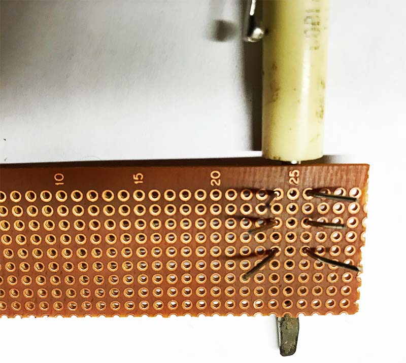
FIGURE 3. Making the clip terminals.
Finally, solder the clips and cut off the excess. Repeat this for all the other clips. Do it carefully and it will look quite nice and provide a convenient way to connect J-clips, alligator clips, or soldered wires. Figure 4 shows the internal wiring.
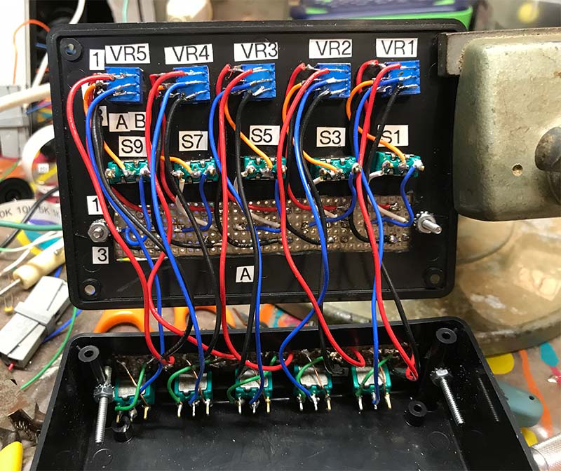
FIGURE 4. Internal wiring.
The lower part of the schematic (back in Figure 2) shows three examples of connection possibilities for typical applications. Example 3 shows a way to get a fine/coarse tuning arrangement. By connecting the 1K and 10K rheostats in series, you can get a variable resistor with the 10K pot being the coarse tune and the 1K pot being the fine tune.
For example, suppose you want to center the fine tuning around 8K. You could set the 10K pot for 7.5K, and then the 1K pot can be used to fine-tune the series resistance from 7.5K to 8.5K. By flipping both switches, you can measure the series resistance between the two pots at the rightmost center clips.
The Parts List shows some alternative materials I would probably use if I were to build another one (which is unlikely, because why would I need two of these?). For one thing, I would probably use single gang pots because (as mentioned earlier) the dual gang pots do not track well enough to offer the real time resistance measurement capability I had hoped for.
For another thing, toggle switches are expensive. I happen to have a generous supply, but if I had to be buying switches, I would probably opt for the less expensive slide switches. A larger enclosure might be required if you use pots that are physically larger than the ones I used.
The knobs are highly recommended, despite the cost. Turning those little 1/8” shafts with fingers is not easy. Figure 5 shows my experiment with the 1K rheostat connected to my oscillator circuit. The ohmmeter is also connected to the box but isn’t doing anything here because the switch is flipped to the left.
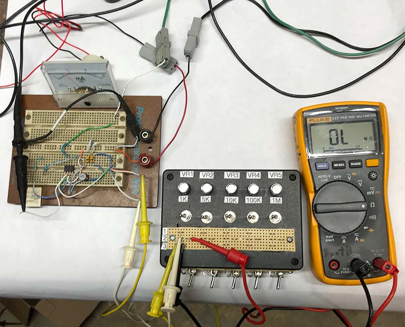
FIGURE 5. Rheostat switched into the circuit.
Figure 6 shows the same thing but with the switch flipped to the right.
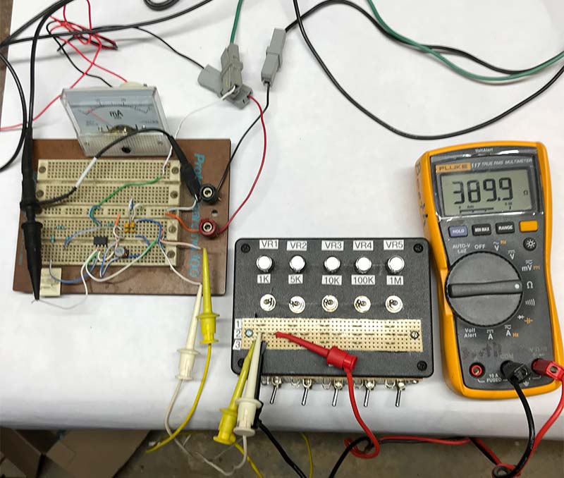
FIGURE 6. Rheostat switched to the ohmmeter.
Now the ohmmeter reads the rheostat resistance while the rheostat is isolated from my oscillator circuit. After noting the resistance, I flip the switch back to the left and the rheostat is once again part of my oscillator circuit.
Now that I’ve built and used this project for my experimenting, my only regret is that I did not do it sooner. NV
Parts List
| Part |
Digi-Key # |
| Enclosure Bud Industries CU-389 |
377-1220-ND |
| 1K 1/4W Linear Dual Potentiometer |
3310H-001-102L-ND |
| 5K 1/4W Linear Dual Potentiometer |
3310H-001-502L-ND |
| 10K 1/4W Linear Dual Potentiometer |
3310H-001-103L-ND |
| 100K 1/4W Linear Dual Potentiometer |
3310H-001-104L-ND |
| 1M 1/4W Linear Dual Potentiometer |
3310H-001-105L-ND |
| Knobs (5) |
679-3543-ND |
| Vector Board |
V1046-ND |
| Toggle Switches (10) |
EG2350-ND |
| Paper Clips Omni #201 ‘Gem Clips, #1 Smooth Finish Light Wire .036 Wire’ (Box 100) |
|
| Alternates: |
| Instead of vector board, use Adafruit Perma Proto 1609, Digi-Key 1528-1195-ND (smaller and much less $$$). |
| Instead of toggle switches, use slide switches such as Digi-Key EG1901-ND (much less $$$). |
| Instead of the dual gang potentiometers, use the single gang pots as follows (less than half the cost of the duals): |
| 1K 1/4W Linear |
3310Y-001-102L-ND |
| 5K 1/4W Linear |
3310Y-001-502L-ND |
| 10K 1/4W Linear |
3310Y-001-103L-ND |
| 100K 1/4W Linear |
3310Y-001-104L-ND |
| 1M 1/4W Linear |
3310Y-001-105L-ND |