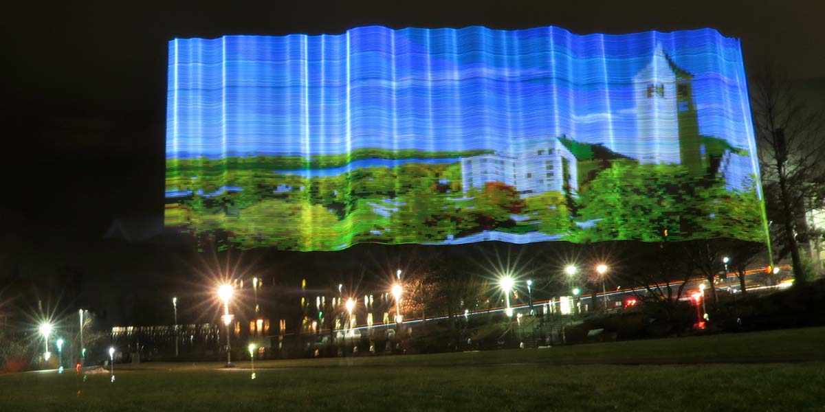
Long exposure photography captures the path of light over time, smearing moving elements to produce a single photo which creates a new realm of artistic photography. However, popular subjects of light exposure photographs are uncontrollable (stars, car headlights, etc), so we made a light painter using microcontrollers and a DotStar LED strip to develop custom photography from images uploaded by a user as part of our final class project at Cornell University.
High Level Design
In order to recreate images, we needed to treat the LED strip as a single column of pixels in a photograph. We decided to reassemble the images column by column to encourage a greater variety of image widths, allowing more room for customization by the user.The LED strip was mounted to a wooden pole carried by a cart that moved using two motors. In short time intervals, the LED strip changed corresponding to a new column of pixels while the cart moved at a constant velocity. From a distance, a user can utilize a DSLR camera to capture the long exposure effect.
To upload and display the image, we used a PIC32 microcontroller (MCU) and a Raspberry Pi Zero W. The RaspPi was enlisted to communicate with the user over Wi-Fi, allowing them to upload an image from the Internet by specifying a URL through the network protocol SSH. The RaspPi was also used to resize the image using Python’s imaging library and to transmit the RGB (red, green, and blue) image data to the PIC32. Upon receiving the RGB pixel values, the PIC32 (connected to the LED strip and motors) converts the pixel data into the protocol RGB values for the LED strip and changes the colors at an appropriate speed. By synchronously changing the LED values and powering the motors, an image is recreated as if hovering in air.
Mechanical/Hardware Design
We mounted the 144 LED/meter DotStar strip on a thin three foot piece of wood. The wooden stick was mounted onto a cardboard box that contained the RaspPi, PIC32, breadboard, and power supplies. The box sat on a wood frame that was connected to the motors and wheels, allowing the mechanism to move in one direction of any distance as shown in Figure 1.
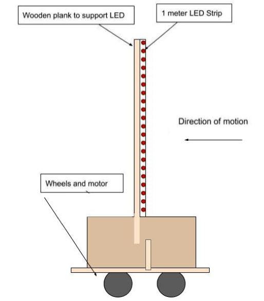
FIGURE 1. Mechanical design.
Since the box itself doesn’t emit any light, it’s not visible in the long exposure photos, so the image appears to be floating in air. Even though the LEDs were closely spaced (144 LEDs/meter), it was still possible to single out the light path of each LED. To recreate our images, we thought it would look best to diffuse the light even more by adding a light diffusing material on top of the LEDs.
We carefully taped five layers of tissue paper on the LED strip to help diffuse the light and create a more blended image without sacrificing light intensity. As shown in Figure 2, using one layer was not enough because you can still single out the individual LED light paths. Using nine layers was too thick as it compromised the light intensity and color. So, the middle ground at five was chosen.
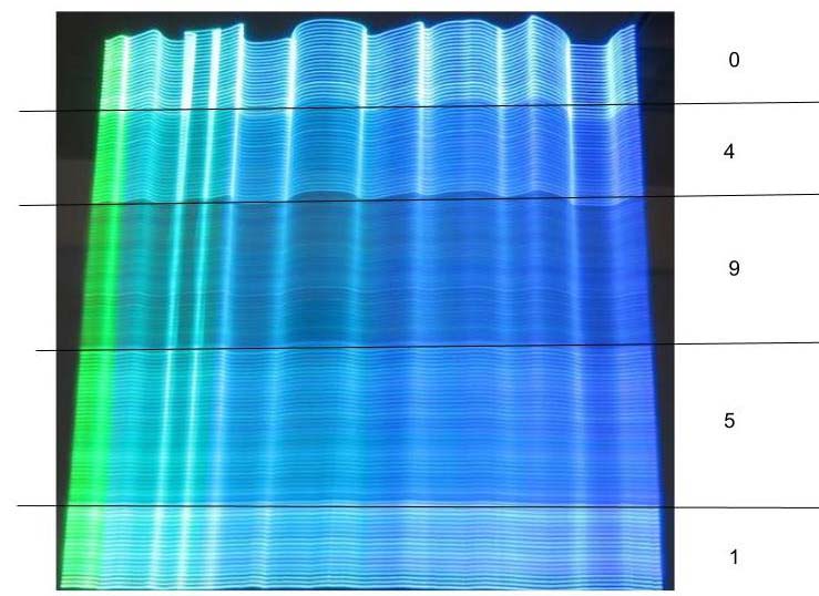
FIGURE 2. Tissue paper layering test showing the result and number of layers used.
The RaspPi Zero had 3.3V GPIO outputs, meeting the required voltage of the PIC32, so the devices were simply connected through 330Ω resistors to limit current and protect the microcontrollers.
We decided to connect the RaspPi Zero to the PIC32 through parallel connections with two different enable pins. We chose unidirectional parallel communication because of our familiarity with this specific data transfer method.
To send the data in parallel, we sent 24-bit RGB values through eight GPIO ports (see Figure 3). Each color was converted from an eight-bit color code to a two- or three-bit color code that was sent to the PIC32. The color data was truncated to transmit data faster and more reliably at the sacrifice of higher color resolution. The PIC32 then converted the color code back into a 24-bit value for the LED strip to display.
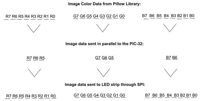
FIGURE 3. RGB color code conversions and data transfer timing diagram.
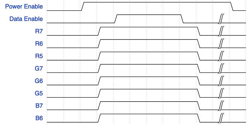
FIGURE 3B. Parallel connection data lines, showing that the first LED in the first column will be white.
To control the RGB color data, the RaspPi implemented a data enable pin that indicated when the color for each LED was sent, and a power enable pin that indicated when to start and stop the motors. This pin allowed us to start the motors upon data transfer and stop the motors once all the data has been sent and the image has been completed.
The power enable pin signaled the start of the image and controlled when the motors were turned on and off. The two motors were connected in parallel, controlled by a PWM (pulse-width modulation) output. We chose to power the motors with a 37.5% duty cycle as this gave the motors just enough speed to move slowly; allow the LEDs enough space to change every few centimeters; and carry the relatively heavy cart. Because DC motors are inductive loads, the release of the stored energy at the end of the PWM cycle causes harmful voltage spikes that could damage the MCU.
To protect the MCU, an opto-isolator was used to electrically isolate the motor from the MCU. Additionally, a diode and capacitor were used to moderate the motor voltage during the PWM transitions. A MOSFET was used to switch the motor on and off using the PWM enable, and resistors were added to protect and optimize the circuit as shown in the complete schematic in Figure 4.

FIGURE 4. Complete schematic.
Since the LED strip requires 5V data and the PIC32 only outputs 3.3V, the DotStar LED strip was connected to the PIC32 through a buffer, 74LS125, that acted like a 3.3 to 5V level shifter using an external 5V power supply (refer again to Figure 4).
The RaspPi, PIC32, and LED strip were powered at 5V through a USB connected power bank with a 5V 2A output. This was possible by running the LED strip at the lowest intensity where it would draw less than one amp, even though the LED strip had a maximum current draw of about six amps. The motors were also powered using a separate 5V power bank that was connected through a USB cable.
Software Design
All the PIC32 functions were in a single thread reading data from the RaspPi, controlling the motors and transmitting the data to the LED strip — all of which is completed in a single thread as the PIC32 has no other functions (see Figure 5).
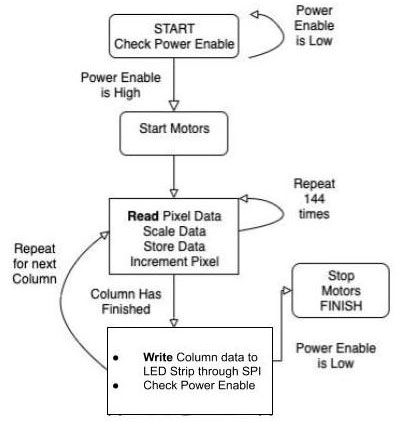
FIGURE 5. PIC32 software schematic.
The PIC32 first waits for a command from the RaspPi power enable pin, signifying that the image is ready. It then starts the motors by changing the PWM motor enable pin from having a 0% to a 37.5% duty cycle. After that, an embedded for loop is used to read the individual pixel data in a single column and send the full column of data to the LED strip through SPI.
After each column is sent, the power enable pin is checked to see if the image has finished. If the image has been completed, the PIC32 will set the PWM duty cycle back to 0% to stop the motors.
Before the PIC32’s thread is initialized, the program contains a few initial setup calls. A timer, output compare module, and output pin are opened for the PWM waveform. Timer 2 is opened with a generate period of 40,000, which corresponds to a frequency of about 1 kHz. This timer is used to generate the PWM pulses necessary for precise motor control.
After opening the timer, the program continues to open Output Compare 3, which is used to send the PWM signal to the motor control circuit. The output compare works off a pwm_on_time, which corresponds to the amount of time to hold the PWM signal high, translating to a faster motor. The motors should be off initially, so pwm_on_time is initialized to 0. After opening the timer and output compare, the PWM initializations are complete. To send data to the DotStar LED strip, an SPI channel is opened for data transmission. After these three modules are opened and configured, the single thread is initialized and prepared to run.
The thread first turns the LEDs off and waits for the RaspPi to send data. To turn the strip off, the RGB values of all pixels are set to 0. Once the transmission has started, the thread continuously reads the data and sets the LEDs in a continuous loop.
In the loop, the function calls to read RGB data (read_pixeldata), set RGB data (set_pixel_rgb), and write RGB data (write_pixels). In “read RGB data,” the pixel data is read and scaled appropriately for the LED strip. “Set RGB” data stores the data into an array, and after all 144 pixels have been stored, “write RGB data” turns on the motors and sets each individual LED to complete one column of pixels. The process repeats until the image is finished, which is signified by the low power enable input. The motors are then turned off.
Each call to read_pixeldata reads the parallel data lines once, corresponding to one pixel’s worth of RGB data. So, to get RGB data for one column of 144 pixels in an image, you must call read_pixeldata 144 times.
Inside read_pixeldata, the function checks the data enable pin. If the data enable pin is low, the pixel data hasn’t been sent yet, so the function will sit in a while loop until the data enable pin goes high, meaning all eight of the parallel input pins have been set to their correct values by the RaspPi.
While waiting for the data enable pin, the function also checks the power enable pin in case the image is complete. If the power enable pin is low, the motors are turned off.
Once the data enable is high, the PIC32 will read all eight input pins, concatenate the bits for each color, and scale the color value back to 24 bits so that it can be sent to the LED strip. Before returning the function, the PIC32 waits for the RaspPi to set the data enable pin to low, signifying the end of that pixel’s transmission.
After read_pixeldata returns with one pixel’s RGB data, setpixel_rgb is called to add that data to a global pixel array which will hold the RGB data of all 144 pixels. The data stored for each pixel is the red, green, and blue color values and the intensity which is globally set to 1 — the lowest possible intensity.
Like read_pixeldata, this function adds one pixel’s data entry at a time, so it must be called 144 times to store all the LED data for the strip. This function was given to us by our instructor, Bruce Land as part of his DotStar LED strip walkthrough.
After all 144 pixels have been read and properly stored, the program still needs to perform the SPI transfer, allowing the strip to display the pixels. Write_pixels takes the global pixel array and sends it out through the SPI channel to the strip.
First, in accordance with the DotStar SPI protocol, a START_FRAME is transferred, followed by 144 PIXEL_FRAMES which each contain one LED’s RGB and intensity data. Finally, a STOP_FRAME is transferred, signifying the end of the transmission and visually lighting the strip.
Once a column has been completed, the thread must read, set, and write the pixels continuously until the whole image is complete. Once the image is complete, the motors will stop and the PIC32 must be reset to project a new image.
RaspPi Software
The RaspPi Zero W was used to retrieve the images from the Internet, and parse and format the RGB data to send to the PIC32 for display. All the necessary code was condensed into a single .py file that was run wirelessly through SSH.
To begin, the user can specify a URL of an image. The RaspPi will download it and rename it to a user-specified file name. Once the file is downloaded on the RaspPi, it will prompt the user for the filename containing the image to be displayed using the DotStar strip.
After the RaspPi imports the file, the 10 GPIO ports are set up as outputs, and the power enable pin is immediately set low. Then, the program opens the image file and uses the Pillow library — a fork of the Python Image Library (PIL) — to resize the image to fit the 144 pixel height constraint. Once the image is properly sized, the program iterates over all the pixels in the image and scales the RGB data. Once the colors are scaled, all the RGB data is saved in a multi-dimensional array.
After the pixel data has been stored, the RaspPi is ready to send the data to the PIC32. First, the starting LED sequence is sent to the PIC32 to visually indicate to the photographer that the image will begin after a three second countdown, after which they should start the long exposure.
To do so, a for loop is used to sequentially change the LEDs and delay for one second. Then, the RaspPi can send the image data using a nested loop (the outer for the rows, the inner for the columns). To send an LED’s data, the multi-dimensional pixel array data is accessed, and the corresponding GPIO pins are set low or high.
Once one pixel’s worth of data is transferred, the data enable pin toggles to signal to the PIC32 that the data lines are all valid values to read (refer back to Figure 3). The process then repeats until the entire image data has been transferred. Once finished, the power enable line will be set low, signaling the PIC32 to stop the motors.
Conclusion & Results
We are very pleased with how our project turned out (see the images).
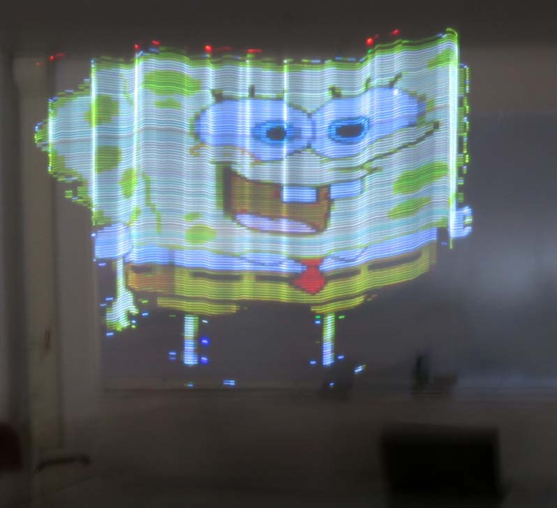
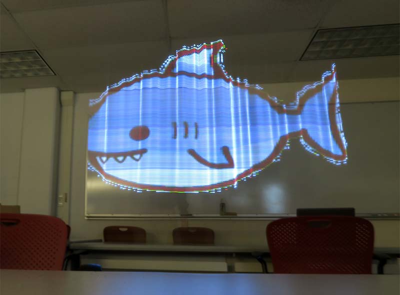
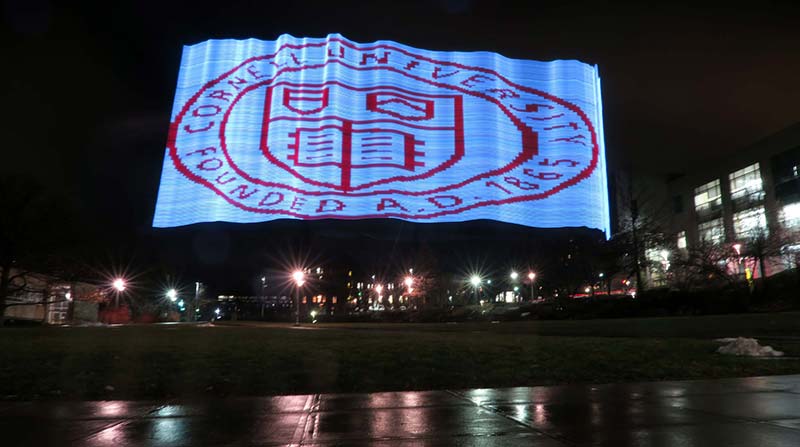
Different images we created.
We successfully programmed and built a mechanism to draw any image using an LED strip and a long exposure camera.
The small motors were able to carry the cart at a continuous speed. The speed and data transmission time were well synchronized, producing compact images that weren’t too stretched out.
The device was also able to display photos with varying widths, from the infamously square SpongeBob SquarePants to long mountainscapes.
Additionally, we liked the effect of reducing the color data. By having less color variability, there was a greater contrast between the colors, producing more cartoon-like images.
Transmitting the image over Wi-Fi was also a convenient feature because it let the user choose and upload a photo from a distance, allowing the device to be used and controlled by the photographer. To watch our project video, go to https://www.youtube.com/watch?v=1LS0P5ddWkc&feature=emb_logo.
Though the DotStar Light Painter was able to produce images effectively, color accuracy was lost from reducing the 24 RGB bits to eight RGB bits.
Additionally, because we only had 144 LEDs per meter, resolution was also lost from the original image (depending on the original resolution of the image).
To increase the resolution, another LED strip could be added. Also, the LED strip could have performed at a higher speed if we had the RaspPi send all the image data at once. However, since the RaspPi sends the data column by column, there is a bit of delay. For us, the delay worked to our advantage because of our slow motors.
The slow speed of the motors was due to too much stress from the torque of the box and LED strip, so motors with a higher torque tolerance would also have allowed us to better tune the images.
Lastly, our mechanical design could have been sturdier. The cart rocked from side to side as it moved, creating warped images. This could have been prevented through a sturdier design, better materials, and a wider wheelbase. NV
Parts List
- DotStar 144 LED/Meter Strip Black
- Raspberry Pi Zero W
- One Meter Wooden Plank
- Motors x2
- Continuous Rotation Servo
- 8x8x8 Cardboard Box
- 5V 2A PureGear Battery Pack
- Wheel x4
- MicroStickII
- PIC32
- Big Board
- Wires
Resources
Adafruit Dotstar Documentation
http://people.ece.cornell.edu/land/courses/ece4760/PIC32/index_pixel_strip.html
Adafruit Dotstar Connections
https://learn.adafruit.com/adafruit-dotstar-leds/power-and-connections
Adafruit Dotstar Code Reference
http://people.ece.cornell.edu/land/courses/ece4760/PIC32/Pixel_Strip/Dotstar/DotStar_test_rgb.c
74LS125 Datasheet
https://www.futurlec.com/74LS/74LS125.shtml
Motors Circuit Reference
http://people.ece.cornell.edu/land/courses/ece4760/labs/f2019/lab3_2019.html
Motors PWM Reference Code
http://people.ece.cornell.edu/land/courses/ece4760/labs/f2019/lab3_2019.html
Image Alterations
https://pillow.readthedocs.io
Project Background
https://learn.adafruit.com/dotstar-pi-painter/overview
PIC32 Schematic
http://people.ece.cornell.edu/land/courses/ece4760/PIC32/Target_board/Large_board_sch_image.PNG
Downloads
What’s in the zip?
C and Python Code Files
Schematic