This project implements a clock/timer device with several useful features other than just a simple alarm. There were actually several “firsts” for me in developing this project: 1): Using a 16-bit PIC (24FV32KA304); 2): Although I’ve had years of experience in C programming, this is the first time for a PIC, (I previously used assembly language and eight-bit PICs); 3): Using the MPLab Code Configurator (MCC); and 4): Using a serial LCD.
*This article does not contain the details of all the menu options. Those are available with the article downloads.
Important to note for this system is that the only difference between an alarm clock and a timer is that an alarm has the speaker set as one of its output devices. Also, all the timed events occur at the “top” of the minute; when the internal seconds value transitions from 59 to 0.
I had four goals in mind with this project:
- Build a working alarm clock with timer capability.
- Develop a generic menu system for a four-line LCD.
- Develop a simple-to-use driver for a serial LCD.
- Use C and MCC to develop the code.
Some general features (in no particular order) of the clock/timer include:
- Four-line serial (I2C) LCD.
- Menu system using a quadrature encoder (QE) with built-in pushbutton for menu navigation, along with two pushbutton switches.
- Nine identical independent alarms and/or timers.
- A speaker for the alarm clock, plus four open drain outputs.
- One output can drive an internal relay with two form C contacts.
- Uses a PIC24 (16-bit) processor programmed in C.
- Provision for internal battery in case of power failure.
- Allows either 12 hour or 24 hour display.
- Option to display seconds.
- Auto detect for Daylight Savings Time.
- Automatic LCD brightness control (two levels).
- Can display starting and ending times of up to 10 power failures.
- Select between two date formats: MM/DD/YYYY or DD/MM/YYYY.
Main Display
The four lines of the LCD are used to display the following (refer to Figure 1):
- Time of day: If a 12 hour display has been selected (default), AM or PM will also be displayed. If DST has been enabled, there is a single character showing either Standard time or Daylight Savings time. If there has been a power failure, a P will be displayed as the first character on the line.
- Day and date.
- Battery status.
- Status of the next alarm (if there is one) and the day and time it’s scheduled to be activated.
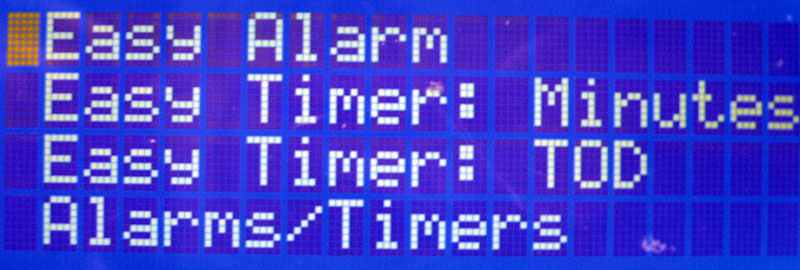
FIGURE 1.
Main Menu
The main menu is entered by pressing switch 1 (the pushbutton of the quadrature encoder). These are the selections:
- Easy Alarm
- 1 Time Alarm: Minutes
- 1 Time Alarm: ToD
- Alarms/Timers
- Current Time/Date
- Easy Defaults
- Utilities
- Build Info
Note for each menu level: The first entry for each level is prefixed by a colon (:) so that you can easily tell when you’ve navigated to the top of the list of menu items.
The Easy Alarm is implemented as a simple alarm clock. The program will search for an available alarm/timer. If you have used all nine, it will tell you there are none left, at which point you’ll need to make one available by deleting one you don’t need.
The program asks only for the alarm time. All the other parameters are set to default values. These values are currently:
- Days of the week set to Monday–Friday.
- Tone frequency to 440 Hz.
- Stop time is set to the alarm time +1 minute.
- Set to repeat weekly.
The 1 Time Alarms were essentially a last-minute enhancement after I had used the timer function on our kitchen stove (“kitchen sink” syndrome?). As with the Easy Alarm, the program will search for an available alarm/timer. All you need to do is enter the number of minutes from “now” or the time of day for when you want the alarm to sound. The default parameters are:
- Days of week is set to today, unless the time falls into tomorrow.
- Tone frequency to 520 Hz.
- Stop time is set to the alarm time +1 minute.
- Does not repeat weekly.
Also, once the alarm is stopped, its data is cleared from memory, making it available.
The default values for both the Easy Alarm and 1 Time Alarms are defined in Project.h. If you want to change these defaults, there are two options: 1): You can edit Project.h, compile the program, and load it into the PIC; or 2): You can modify the default values via the Easy Defaults menu option.
The Alarms/Timers menu allows you to completely define all the parameters for any selected alarm/timer.
The time and date values may be entered via the Current Time/Date menu option. However, when the system is started for the first time, it will prompt you to enter the current time and date.
When entering the time, it’s best to accept the entered minute value at the “top” of the minute — when seconds changes from 59 to 0. This means that you should use a clock reference that accurately displays the time of day to the second.
There is also an option to calibrate the timer used for the one second counter.
The Utilities menu has several options which are usually set only once:
- Snooze time — a global value for all alarms.
- Timer divisor — allows you to modify the divisor used for the one second counter. This is the crystal frequency divided by two. You can use this to manually calibrate the clock.
- Show the times and dates of up to 10 power failures; requires that a backup battery be installed.
- Enable/disable DST detection.
- Enable/disable displaying of seconds.
- Allow the direction bit of the QE to be inverted.
- Set the trip level for the LCD brightness.
Alarm Clock/Timer Configuration
The alarm clocks and the timers are set up in the same way. When you select Alarms/Timers - Full Setup to configure an alarm clock or timer, the system prompts you to enter the following data:
- Which alarm you want to use.
- Start and stop times.
- Days of the week.
- Outputs: Speaker and/or up to four open drain outputs.
- If the speaker is one of the selected outputs, tone frequency with 8 Hz resolution.
- Whether or not the alarm is to be repeated weekly.
- Whether or not to enable the alarm.
- Whether or not to save the alarm configuration to EEPROM.
It may seem odd to have a stop time for an alarm but there are some reasons why I did it. First, it was easier since this system can also be used for programmable timers which do require a stop time.
I also thought it would be a good idea to stop the speaker after a while if no one is around to turn it off. The start time will initially be set to the current time and the stop time will be set to the start time +1 minute.
The days of the week entry allows you to select any combination of days for which you want the alarm/timer enabled.
For the alarm feature, you must select the speaker output. You can also select any combination of the other four outputs.
When the speaker is selected, you’ll be prompted to enter the tone frequency you want for this specific alarm. The speaker in the Parts List has a reasonably good response from 200 Hz up to about 1,500 Hz and is loud enough for a wake-up alarm — unless you’re a very sound sleeper. A larger speaker will usually be louder.
There is currently no provision for volume control. If you feel you want one, it can be easily accomplished by inserting a variable resistor in series with the speaker.
When the alarm gets activated at the start time, it will pulse on and off with a 50% duty cycle and a two second period.
The repeat feature allows you to have the alarm repeated from week to week as opposed to one time only.
The enable feature allows you to keep the configuration but temporarily disable the alarm/timer. The enable status may be changed via the menu: Alarms/Timers - Detailed Setup - Enable/Disable.
Saving the configuration to EEPROM guarantees that the values will be restored after a power failure and when the battery is too low to maintain operation.
Alarm Operation
The switches of the clock/timer have different effects depending on when the switch is pressed. If an alarm is “ringing,” pressing any switch will turn off the speaker. If you press switch 1 (the pushbutton of the quadrature encoder), the alarm will remain enabled for the next configured day. Pressing switch 2 will activate a “snooze” timer which has a default value of 10 minutes. You can reactivate the snooze as many times as you like.
The snooze time — which is global for all alarms — is configurable via the Utilities menu. Pressing switch 3 currently does the same as switch 1.
When the alarm is not ringing, pressing switch 1 will enter the menu system. Pressing switch 2 will toggle the enable state (on/off) of the speaker if an alarm is active. The speaker will be re-enabled at the next alarm start time. Switch 3 does nothing at this time.
Menu Subsystem
The menu is hierarchical and allows up to seven nesting levels, but is limited to a maximum of 20 entries for each level. The example that follows shows three nesting levels. Both the number of nesting levels and entries per level can be increased by modifying the menu files.
There are three files specifically for the menu subsystem: Menu.c; Menu.h; and Menu_IO.h. These three files can be migrated to another project fairly easily.
Neither Menu.c nor Menu.h should need to be modified. Menu.h contains the function prototypesw and detailed descriptions of each of the user functions available in Menu.c.
Menu_IO.h has two main sections used to customize the menu operation:
- A set of defines which allows you to select the functions within Menu.c that you need for your application. This was implemented so that unneeded functions do not take up program memory space.
- A set of hardware definitions that defines the I/O pins for the three pushbutton switches and QE.
The menu system also requires several functions from the LCD library that we’ll discuss next.
I’ve already used the same menu files in another completely different application; all that was changed were the two sets of definitions in Menu_IO.h.
To use these files, you’ll have to create a structure in your main program file containing the menu items. As an example:
const Menu_t MyMenu[] =
{
{0, 0, “”, 1}, // top of menu list
{1, 0, “:Title 1”, 1},
{ 2, Function_1.1, “:Sub Title 1.1”, 1},
{ 2, Function_1.2, “Sub Title 1.2”, 1},
{ 2, 0, “Sub Title 1.3”, 1},
{ 3, Function_1.3.1, “:Sub Title 1.3.1”, 1},
{ 3, Function_1.3.2, “Sub Title 1.3.2”, 1};
{1, 0, “Title 2”, 1},
{ 2, Function_2.1, “:Sub Title 2.1”, 1},
{ 2, Function_2.2, “Sub Title 2.2”, 1},
{0, 0, “”, 0} // end of menu list
};
The qualifier const is not necessary. It’s used to force the structure into Flash memory. Without the qualifier, the structure would be placed into RAM.
The indenting shown is simply to make it easier to see the hierarchical nature of the menu. There are four items for each menu entry:
- The menu level, with 1 being the outermost level (0 is the indicator the program uses to detect the beginning and end of the structure).
- The address of the function to execute if the menu entry is selected. For those entries which are “parent” entries, the function should be 0; that is, no function gets executed when it’s selected. If a function is listed, it will be ignored.
- The title of the menu entry. It must be less than 20 characters in order to fit on one line of the LCD.
- A constant value which is passed to the function. This value may be used to indicate whatever might be useful for your application. In the clock program, one use is to signal whether the function is being called via the menu vs. when it’s called by another function.
Menu_t is the structure definition type and is defined in Menu.h. Here is its current definition:
typedef struct
{ uint8_t Level:3; // limit to 7 levels
int8_t (*Function)(int);
char Name[19];
int Param;
} Menu_t;
The system has been implemented such that it would not be difficult to add to or change the structure to meet your requirements. For instance, the last item for each entry is currently defined as an int. It would be very easy to change it to a float by changing the parameter type in the Menu_t structure definition and a one line edit of the DoMenu function. The only limitation is that all the menu functions must have the same data type as their only parameter.
The following code shows how to execute the menu function:
DoMenu ( (Menu_t *)MyMenu );
DoMenu is the name of the function in Menu.c which executes your menu code. The reason for casting the type is because the menu in the main program is declared as a const Menu_t, whereas Menu.c only requires Menu_t. This allows the menu to be placed in RAM if desired.
There are several functions available in Menu.c to help you develop code for using the menu system:
- EnterText: Allows you to enter text via the quadrature encoder and the switches.
- Select_N_on_Line: Allows you to display several options on a single line and select any combination of them.
- Select_1_on_Line: Allows you to select only one of several options on a single line.
- Select_1_of_List: Allows you to select one item from a list. The list can be any length, but each entry must fit on a single line.
- Yes_No: Allows you to select between Yes and No.
- Int_to_ASCII: This one converts an integer to ASCII. The only reason for this function is because the sprintf function added about 6 KB to the code.
- FP_to_ASCII: Convert a floating-point value to ASCII.
All the functions above have an enable macro in Menu_IO.h which allows you to enable or disable the function from being used when the program is compiled. For this program, EnterText and Select_1_of_List are not enabled:
- WaitPB: Wait for a specified pushbutton switch closure and release.
- WaitSwitches: Wait for any switch, including the QE. If a pushbutton is detected, it will wait for its release.
- ReadPBs: Read the state of all the pushbutton switches.
- Delay: Wait some number of milliseconds.
All three switch functions have some debounce code in them.
LCD Subsystem
Although I’ve used HD44780 interfaced LCDs many times in the past, the interface was always parallel. In order to save I/O lines, I wanted to try serial this time. I’m quite familiar with SPI but not so much with I2C, so I thought I would give it a try.
The I2C displays I found all seemed to use the same method: a PCF8574 IC which has an I2C input for control and an eight-bit parallel output. These outputs are divided among a four-bit data bus: three bits for LCD control (RS, R/W, EN); and one bit for an LED backlight.
I developed four files for the interface, similar to the menu files: LCD.c which is hardware independent; LCD_IO.c which has the hardware dependent functions; LCD.h; and LCD_IO.h. Again, I’m using the same files in another completely different application where only LCD_IO.c and LCD_IO.h were modified.
The functions available in LCD.c are:
- LCD_Char: Print a single character.
- LCD_Clear: Clear the LCD screen.
- LCD_ClearLine: Clears a specified line by filling it with spaces.
- LCD_Cursor: Set the cursor type.
- LCD_Pos: Set the cursor position.
- LCD_Line: Get the current line number.
- LCD_Column: Get the current column number.
- LCD_Print: Print a null terminated string.
- LCD_PrintN: Print a specified number of characters.
None of these functions know anything about the hardware interface. They are, however, aware of the size of the LCD.
There are only three functions in LCD_IO.c which are called from other files:
- LCD_Initialize: Called from the main program to initialize the LCD hardware.
- LCD_Cmd: Send a command byte to the LCD, called only from LCD.c.
- LCD_Data: Send a data byte to the LCD, called only from LCD.c.
None of these three functions are aware of the type of interface being used.
There are three functions in LCD_IO.c that are hardware specific and are used only by LCD_IO.c:
- LCD_Byte: Send a command or data byte to the LCD.
- LCD_Nibble: Send a four-bit value to the LCD.
- I2C_Send: Send a series of bytes to the PCF8574.
Just a note of interest: It takes four bytes to the PCF8574 in order to send a single byte to the HD44780.
Hardware
The hardware design is based on a 16-bit PIC24FV32KA304. Although it has an internal Real Time Clock (RTC) feature, I found it easier to implement my own code for the clock function. I also attempted to use its internal high speed oscillator for my clock reference but it’s not stable enough, so there’s an external crystal oscillator.
In searching for an oscillator, I first thought I would look at SMD units. The only one I found that I felt was suitable was a no-lead package which would be difficult to solder by hand. So, I ended up with a half size can unit.
The oscillator frequency is 8 MHz simply because I happened to have one in my parts bin. You can easily use a different frequency, as long as you edit the program using MCC. The program has a calibration option which can compensate for inaccuracy in the crystal frequency, but it cannot compensate for instability.
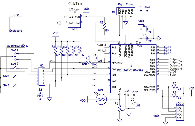
Schematic 1 shows the connections for the PIC, QE, pushbutton switches, LCD, and programming connector.
SCHEMATIC 1.
You don’t have to use the specific quadrature encoder I have in the Parts List; just about any kind will work as long as there is no active circuitry required. The one I have specified has a pushbutton included.
I also prefer one that has at least 16 pulses per revolution as well as detents. You can use a separate pushbutton in place of the one on the quadrature encoder. The pushbuttons can be almost any momentary type you want to use.
The hardware requirements for the LCD are quite minimal. The PCF8574 requires any voltage between 2.5V and 6V to operate. The maximum speed of the I2C bus is specified as 100 kHz. This is slow enough that you can watch the screen being updated, although it’s fast enough for this application. There are only four connections to the LCD plus one for the LED backlight.
Since I wanted to control the backlight brightness, I didn’t use the PCF8574 to be the only control for it. I use the control line only to pull the cathode of the LED to ground. The anode of the LED is connected to a jumper pin, so I implemented a circuit (Q106) to drive this terminal from a PWM output of the PIC.
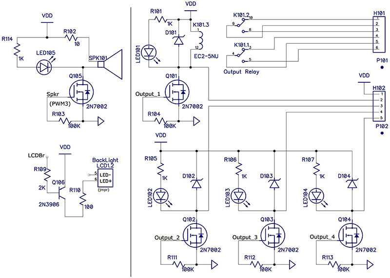
Schematic 2 shows the output circuits of the clock/timer. There is provision for up to four open drain outputs, one of which can also drive a DPDT relay on the circuit board.
SCHEMATIC 2.
The four open drain outputs and the relay contacts are available on two terminal block headers. These headers have a mating terminal block plug with screw terminals for wire connections. I’ve found these connectors to be very handy since they’re pluggable as well as having screw connections.
The PWM for the LCD backlight drives a PNP transistor through a current-limiting resistor which allows for controlling the brightness of the backlight. There are currently two brightness levels used: high and low ambient light. The duty cycle is calculated based on the resistance of a photoresistor (RP1) which senses the ambient light level. The transition point is programmable via the Utilities menu.
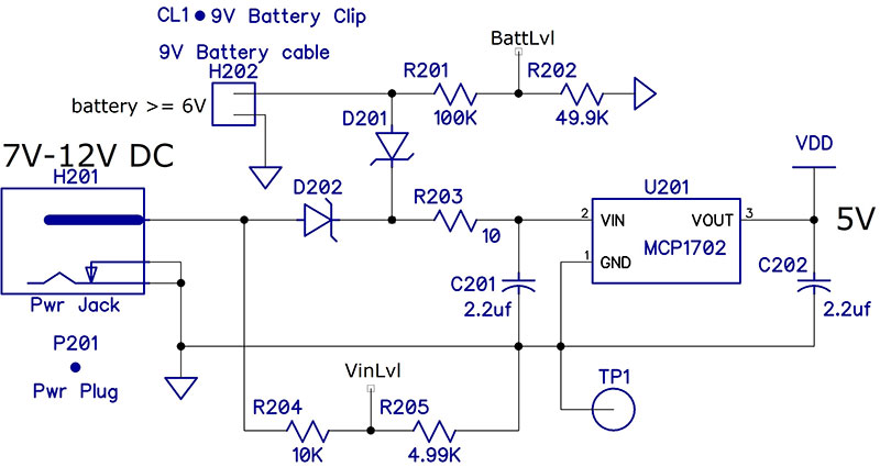
The power supply (shown in Schematic 3) contains a 5V linear regulator and provision for allowing a battery to drive the circuit if the main input voltage fails. This circuit requires that the main power supply voltage be higher than the battery voltage in order to work properly.
SCHEMATIC 3.
I use a 12 VDC wall wart and a 9V battery. I chose the MCP1702 instead of a 78L05 mainly because it has a lower drop-out voltage (650 mV vs 1.7V). It also has a different pinout than the 78L05, so be careful if you use it in your designs.
The unit draws about 27 mA with the brightness set to 50% and about 20 mA with it set to 10%. The better alkaline 9V batteries show a rating of about 400 mAh to a discharge voltage of 6V with a 100 mA load. That should guarantee at least 20 hours for the clock.
The AA batteries show about 1.6 Ah with a 100 mA load to a discharge voltage of 1.2V. If you decide to use AA cells, I recommend that there be five of them to ensure the voltage stays above 5.7V. Note that there is a constant battery drain of 60 µA due to the voltage measurement circuit.
Schematic 4 shows a remote AC solid-state relay (SSR) which can be driven by any of the four open drain outputs of the clock/timer. The circuit uses an optically-isolated triac with a zero-crossing detector. This particular triac can handle over 240 VAC at 1.2 amps and is also available without the zero-crossing detector (some AC loads don’t work well with them).
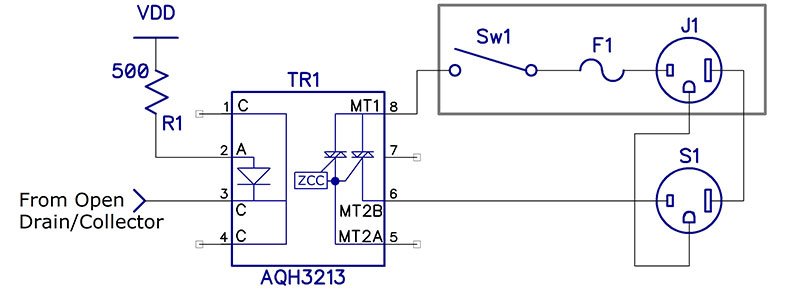
SCHEMATIC 4.
My original circuit had two of these on the circuit board with the rest of the clock/timer circuitry. However, I eventually decided it would be better to have the AC handling circuitry in a separate box; refer to Figure 2.
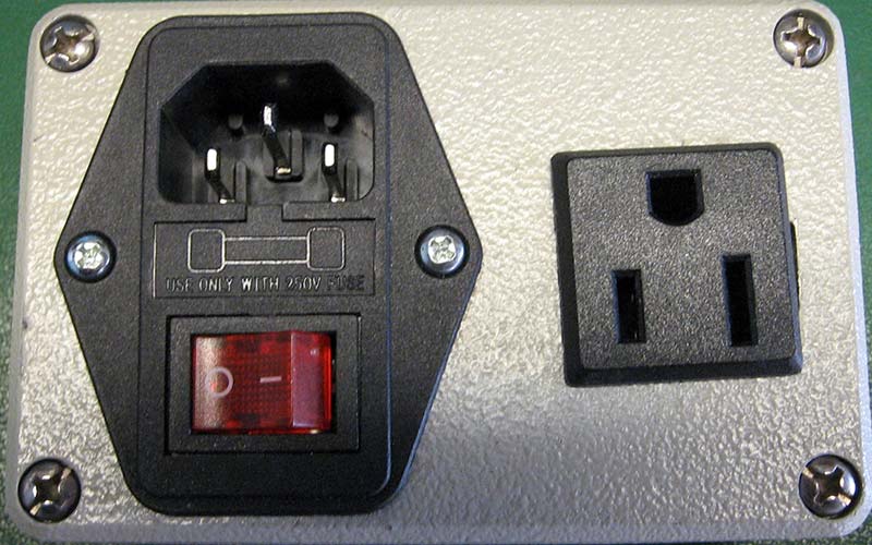
FIGURE 2.
The current-limiting resistors are determined by the value of VCC (5V), the voltage drop across the diode (1.5V max), and the current required by the diode (7 mA):
R = (5-1.5)/.007 = 500 ohms
Only two wires from the clock/timer, VCC, and the open drain output are required to drive one of these circuits. It’s quite feasible to have up to four triacs in the box, each driven by its own clock/timer output.
Construction Notes
- The PCB (printed circuit board; Figure 4) contains the circuits of Schematics 1, 2, and 3.
- The crystal oscillator (mounted on the bottom of the PCB) should be mounted last due to the devices mounted on the top of the PCB. You’ll have to solder one lead from the bottom side, so be sure to leave the leads long enough to get your iron under the can.
- Neither the switches nor the power jack (J201) are mounted on the PCB.
- The main constraint on the box is the size of the LCD. Make sure there is room for the battery you choose to use.
- The PCB is 2.15 x 2.25 inches. I mounted mine on the back side of my enclosure.
- I mounted the programming header on the back of the PCB and cut a hole in the box, so I can program the unit without opening the box.
- The I/O connectors (H101 and H102 if you use them) should also be mounted on the bottom of the PCB and appropriate rectangular slots cut in the box.
- I mounted the three switches on the top of my box; refer to Figure 3.
- There are quite a few build options if you don’t need all the I/O features. For example, a simple alarm clock only requires the speaker and the LCD brightness control circuits. You can eliminate all the rest of the I/O parts. The Parts List shows which components are required for a full build as well as those required for a simple build. Schematic 2 has a vertical line which separates the parts needed for a simple alarm clock from those which use the additional I/O.
- The hardest part of the assembly is handling the SMD components. I typically install from lowest profile to highest. All the SMD resistors and capacitors are 0805 or larger and should be relatively easy to handle. The spacing is such that 0603 parts will also fit.
- The schematic and Parts List indicate headers and sockets for connecting the switches, LEDs, LCD, and power supply to the PCB. You don’t need to use them. You can just as easily solder wires into the header positions on the PCB. I typically use the headers and sockets so that assembly and disassembly is easier for debugging. These items are listed as optional in the Parts List. If you don’t have a crimp tool for the sockets, it would probably be better to simply solder the wires to the PCB and not use the headers and sockets.
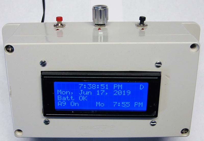
FIGURE 3.
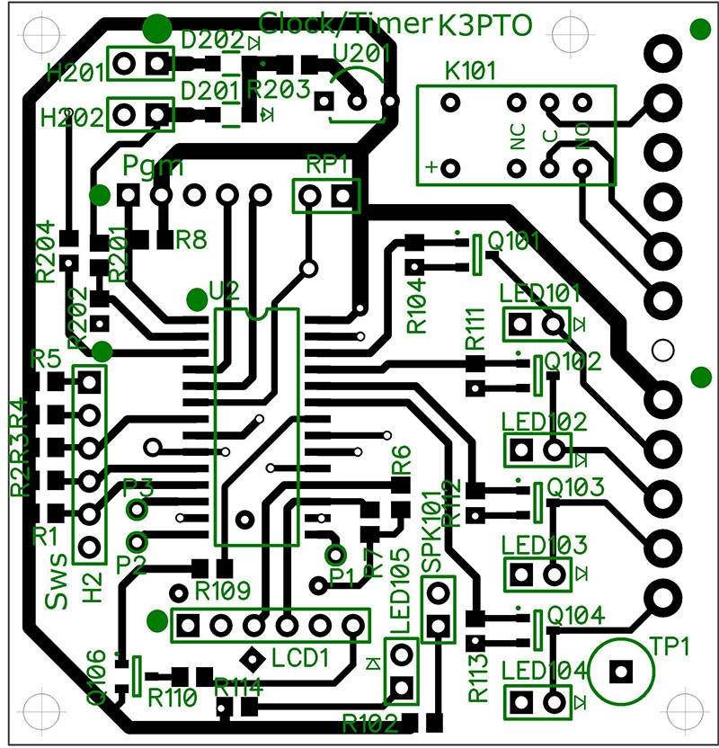
FIGURE 4.
Conclusion
I had a lot of fun learning new things with the clock/timer device. I hope you enjoy your time with it as well. NV
Parts List
| RefDes |
Value |
Digi-Key Part #s |
Qty |
Notes |
Qty Clock only |
| C1, C2, C3 |
0.01 |
311-1136-1-ND |
3 |
|
3 |
| C201, C202 |
2.2 µF |
1276-6458-1-ND |
2 |
|
2 |
| CL1 |
9V Battery Clip |
36-71-ND |
1 |
|
1 |
| D101, D102, D103, D104, D201, D202 |
|
1655-1928-1-ND |
6 |
4 |
2 |
| H1, H2 |
|
S1012EC-40-ND |
1 |
2 |
0 |
| H101 |
|
ED2812-ND |
1 |
2 |
0 |
| H102 |
|
ED2811-ND |
1 |
2 |
0 |
| H201 |
9V Battery Cable |
36-232-ND |
1 |
|
0 |
| J201 |
Power Jack |
CP-011B-ND |
1 |
|
1 |
| K101 |
Output Relay |
399-11052-5-ND |
1 |
2 |
0 |
| LED101, LED102, LED103, LED104, LED105 |
|
C503B-RAN-CZ0C0AA2CT-ND |
5 |
2, 4 |
0 |
| P101 |
|
ED2879-ND |
1 |
2 |
0 |
| P102 |
|
ED2878-ND |
1 |
2 |
0 |
| P201 |
Power Plug |
CP3-1001-ND |
1 |
|
1 |
| Pin1 |
Pins for S1 |
WM2562CT-ND |
25 |
1, 2 |
5 |
| PR1 |
Photoresistor |
NSL-5152-ND |
1 |
2 |
1 |
| Q101, Q102, Q103, Q104, Q105 |
2N7002 |
2N7002LT1GOSCT-ND |
5 |
4 |
1 |
| Q106 |
MMBT3906 |
MMBT3906-FDICT-ND |
1 |
|
1 |
| R1, R2, R3, R8, R9, R201, R204 |
10K |
RMCF0805FT10K0CT-ND |
7 |
1 |
7 |
| R4, R5, R101, R105, R106, R107, R114 |
1K |
RMCF0805FT1K00CT-ND |
7 |
1 |
7 |
| R6, R7, R109 |
2K |
RNCP0805FTD2K00CT-ND |
3 |
1 |
3 |
| R102, R203 |
10 |
RMCF0805FT10R0CT-ND |
2 |
|
2 |
| R103, R104, R111, R112, R113 |
100K |
RMCF0805FT100KCT-ND |
5 |
1 |
5 |
| R110 |
100 |
RMCF0805FT100RCT-ND |
1 |
|
1 |
| R202, R205 |
4.99K |
RMCF0805FT4K99CT-ND |
2 |
|
2 |
| S1 |
Mate for H1 & H2 |
WM5343-ND |
1 |
|
1 |
| SPK101 |
|
433-1151-ND |
1 |
|
1 |
| SW2, SW3 |
PB Switch |
EG5932-ND |
0 |
3 |
0 |
| SW1 & QE |
Rotary Encoder |
987-1188-ND |
0 |
3 |
0 |
| U1 |
8 MHz |
535-9184-5-ND |
1 |
|
1 |
| U2 |
24FV32KA302 |
PIC24FV32KA302-I/SO-ND |
1 |
|
1 |
| U201 |
MCP1702 |
MCP1702-5002E/TO-ND |
1 |
|
1 |
| U301 |
AQH3213 |
255-2660-ND |
4 |
2, 4 |
0 |
| BOX1 |
|
HM225-ND |
0 |
3 |
0 |
Notes
1. Buying in quantity may be cheaper than buying only the number required.
2. Optional — see text.
3. Items purchased via Internet — see below.
4. Quantity is up to the user.
LCD1 - Blue Serial IIC/I2C/TWI 2004 204 20x4 Character LCD Module
SW2, SW3: https://www.ebay.com/itm/NEW-Push-Button-RED-GREEN-YELLOW-Switch-Momentary-On-OFF-Push-Button/382799098852?hash=item59209ab3e4:g:VSMAAOSwOAJcbekh
BOX1: https://www.ebay.com/itm/158x90x64mm-Plastic-Waterproof-Cover-Clear-Electronic-Project-Box-Enclosure-Case/311878356259?ssPageName=STRK%3AMEBIDX%3AIT&_trksid=p2057872.m2749.l2649
If you’d like to build this project and want a single board, you can email me at [email protected] and I’ll send you one for my cost (about $9.50 plus shipping). If you want three boards, you can order them directly from OshPark at oshpark.com/profiles/K3PTO.
If you don’t have PIC programming capability, I’d be happy to program a processor for you if you send one to me.
Both the schematic and board layout were done using DipTrace (www.DipTrace.com). There is a free version available from their website which will handle this circuit.
Check the downloads for this article for all the necessary files.
Downloads
Code
Instructions
MPLAB files


