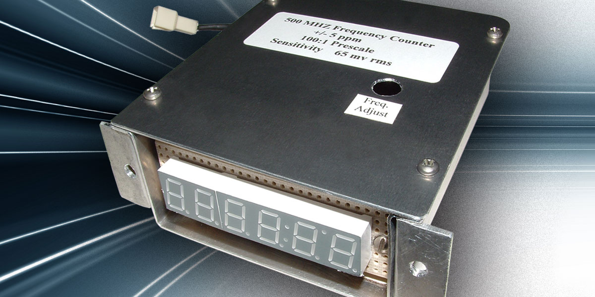
Frequency counters have always fascinated me. Even a mediocre model has higher accuracy than any other instrument on a test bench. My first such counter was a Lampkin micrometer frequency meter which was popular in the mid-1960s. This well-designed instrument was based on a narrow range variable frequency oscillator (VFO) that was tuned with capacitor plates.
The VFO was attached to a modified machinist's micrometer with a calibrated dial plate. After a 15 minute warm-up, the VFO was zero beat to one specific frequency against a very stable compensated crystal oscillator. From that point, each frequency being tested was checked using a lookup table after zero beating the Fo under test to the calibrated dial reading.
According to its specifications, the Lampkin's accuracy was only ±50 Hz. Even so, it performed well enough for my ship-to-shore radio business at the time. My frequency meter's accuracy was far better than the marine radios of that era. They fell in the medium frequency spectrum and rarely had more than six or seven crystal-controlled channels with a Federal Communications Commission (FCC) tolerance of ±100 PPM (parts per million) of carrier.
My meter served me well for years. However, the shift over to VHF gave rise to tighter frequency tolerances and meters with 80 channel capability. I knew it was time to shell out big bucks to replace the old Lampkin with a modern counter with (gasp!) a digital display. In retrospect, as marvelous as the Lampkin's engineering was, its operation almost seems comical to me now.
Frequency Counter Overview
The frequency counters currently on the market offer both high accuracy and ease of use. Even though the circuit actions are complex, the circuit itself is fairly simple. This straightforward circuit design is the result of its minimal analog circuitry, as well as the advent of VLSI (Very Large Scale Integration) logic ICs. These days, a counter whose design is not PIC based tends to follow a very similar design pattern. Figure 1 shows a simplified block diagram of a typical counter.
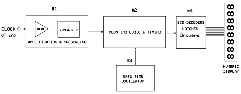
FIGURE 1.
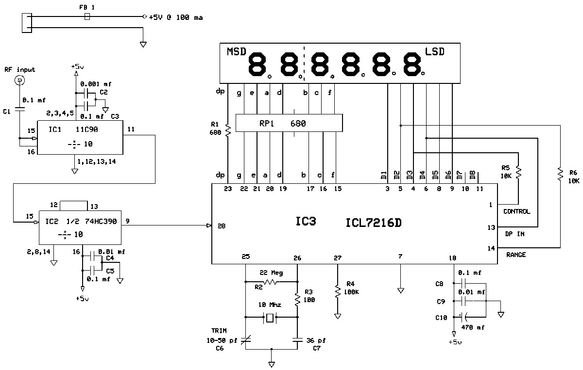
FIGURE 2.
The frequency being measured is labeled here as "clock." The input to block #1 uses a probe with the amplification and prescaling necessary for the counting circuits. Most logic counters are limited to 10 MHz or fewer. If the clock has sufficient amplitude, block #1 can be clocked directly into block #2. However, when frequencies exceed the 10 MHz limit, a prescaler is required to divide the clock signal until its frequency reaches a level that the counting circuits can handle.
Prescaling reduces the counter's resolution, typically by an insignificant amount. When the clock's pulses enter block #2, the counter begins counting every pulse it "sees;" block #3 (the gate time oscillator) determines what the counter sees. The function of block #3 is to produce an accurate time base to gate the incoming clock signal in block #2. This time base is derived from a stable crystal oscillator and divided to a gate time that is typically either a 0.01, 0.1, 1, or 10 second period.
When this gate opens, clock pulses are fed to the counter and it starts counting. When the gate closes, the feed path is blocked, the counter stops, and it holds the last count. For example, when the gate time is 1.0 seconds and the clock rate is 1.0 kHz, exactly 1,000 pulses are counted and held in binary-coded decimal (BCD) format. This requires a four-digit display and four BCD outputs from the counter — one for each digit.
The timing circuits in block #2 ensure that all the requisite operations occur consistently and sequentially. The clock pulses are counted until the gate closes, at which time block #4 is activated. The held count is latched into block #4 and decoded BCD into seven-segment out which drives the segments of that particular digit. Every digit has its own latch, decoder, and driver, and this transfer takes place simultaneously for all digits. Immediately after the latches capture the BCD info, a reset pulse is generated and all counters are reset to zero. Shortly afterwards, the time base gate opens and the process repeats.
Here's a summary of the basic function counter operation:
- The time base gate opens.
- Counting begins.
- The time base gate closes.
- Counting stops.
- Counter info is latched and decoded to digit segments.
- Counter resets to zero.
- The time base gate opens, and the process starts all over again.
A multiplexed display has a similar operation but it is, of course, more complex. In a multiplexed configuration, a low frequency oscillator cycles through the digits and segments continuously, enabling the correct digit and its corresponding segment driver at the same time. The multiplex rate can range anywhere from 100 Hz to 500 Hz per second. This greatly reduces wiring, construction, and overall current drain because only one digit is lit at any point in time.
The frequency counter's overall accuracy is largely determined by block #3 — the time base generator. Any error that occurs is measured in PPM, and it is transferred directly to the displayed readout. The counting and timing circuits are fairly reliable. They have little bearing on overall accuracy, with the exception of the ± one count that occurs in any digital readout. This phenomenon is not a fault in the circuitry but, rather, an occurrence caused by the incoming clock signal not being phase-locked to the time base gate.
If the gate opens somewhere in the mid-point of a high clock signal, it will also close during a mid-point. This will cause the readout to register one more count than the actual clock frequency. Similarly, the readout can lose a count when the gate opens somewhere on a low clock signal. Unfortunately, there is no easy way to avoid this situation. However, since it only affects the LSD (least significant digit), more digits reduce the error.
This article focuses on the construction of frequency counters ranging from a simple retrofit unit to a full-blown universal counter with all the bells and whistles. All of these counters are based on a marvelous chip developed in the 1980s: the Intersil ICM7216 series. I first became aware of this chip 15-20 years ago. At that time, it was no longer in production. These chips were still available but only with a $500 minimum order from secondary suppliers. In spite of these factors, I kept my eye on these chips over the years waiting for them to be affordable, but to no avail.
Frequency counters I built in the interim were "stick built" from multiple single-function logic chips. Each counter required many chips and much wiring to construct. All the while, I was chomping at the bit for those hard-to-find Intersil chips. A few years ago, small time distributors started listing a plethora of electronic ICs from China. Not only were these chips (and many others) now available, they could be ordered in small quantities — even individually — for an affordable price.
Each of the four varieties of the ICM7216 has its own suffix: A, B, C, and D. There are minor differences between the chips, and one will be more suited for different applications than the other. While they all make suitable frequency counters, the A and B varieties have options that enable them to make complete universal counters that can measure period, pulse width, frequency ratio, and totalizing. The A and C versions are designed for common anode displays, while the B and D varieties are for common cathode displays.
These counter chips require very little support circuitry and make construction so much easier than their predecessors. The basic frequency counter only needs a few components in addition to the chip. Adding a few switches enables them to perform practically any function you might need from a universal counter. With such enhancements as an amplifier/prescaler and an external TCXO time base oscillator, your counter can rival most high-end models on the market with an upper frequency limit of 800 MHz or higher, and accuracy exceeding one PPM!
I wrote an article about installing a counter in a 150 MHz RF signal generator. This installation provides an excellent example of retrofitting a frequency counter. When retrofitting frequency counters, the first thing to consider is matching the counter design and the piece of equipment in which you will install it. Factors that come into play include the number of display digits, the accuracy and resolution required, and the prescaling (if needed). For the RF signal generator, I needed at least three display digits because I would be counting in MHz.
Prescaling was necessary since I would be measuring frequencies above the 10 MHz limit of the counter chip. The generator's specs list the limit of its short-term stability as 100 PPM. However, according to my own testing, the stability across its range averaged closer to 20 PPM. That limit equates to either 200 Hz at 10 MHz or 2,000 Hz at 100 MHz.
I wanted to resolve somewhat beyond 2,000 Hz to more accurately measure the average frequency outputs of this generator. I arbitrarily determined that a 1 kHz resolution would be optimal stability across its total bandwidth (0.300-150.000 MHz). It would be pointless to have a resolution of 1 Hz or 10 Hz if the generator was not stable enough to sit in either spot for more than a few seconds.
I determined that I needed to cover a range of 150 MHz with a resolution of 1 kHz which requires six display digits (e.g. xxx.xxx MHz). Since the counter's input frequency limit is 10 MHz, I needed to reduce that 150 MHz input to below 10 MHz. This required a prescaling division of 100 so that the highest frequency the counter would see would be 1.5 MHz.
I recommend prescaling in multiples of ten; doing so simplifies the gate period and timing circuitry. Counter’s digital readouts rarely count the actual frequency displayed. By prescaling in multiples of ten and repositioning the decimal point, the numbers come up correctly (e.g., 150.000 MHz into prescaler, 1.50000 MHz into counter, move the decimal two places to the right, and label readout in MHz; final result 150.000 MHz).
A frequency counter's accuracy and resolution requirements are closely tied. In this particular case, I had a resolution of 1 kHz which equated to 100 PPM (and more when measuring any frequency below 10 MHz), which meant I couldn't discern any error less than this amount. At measurements of 100 MHz, the least discernable error would be 10 PPM. Any accuracy of the counter less than 10 PPM would not even register; due to the stated resolution of 1 kHz, it would need one more digit of resolution to display that error.
The crystal I chose for this application has an overall temperature coefficient of ±30 PPM across its whole temperature range. With the added trimmer cap, it can be set very accurately. Since its primary usage will be in a lab environment, it will probably hold within ±5 PPM in a lab, and that will suffice for this application.
The final factor that I needed to address in this design was the range/counter gate time period. A 1.0 second gate time gives a nice steady display, but is too slow for tuning to any given frequency. A 0.1 second gate is great for tuning since it tracks the frequency as fast as the tuning control can be turned. However, once it reaches the frequency limit, the counter might emit an annoying flicker on the LSD digit. I found the ideal operation has a refresh rate of 0.3 seconds. This rate occurs with a 0.1 second gate time and the chip’s built-in 0.2 second 'between reading' time, thus giving the desired refresh rate of about three times a second.
If I were designing this counter for a higher caliber generator — that is, an extremely accurate and stable one with a 1 GHz tuning range — I would probably end up with eight digits and a resolution of 100 Hz, plus an accuracy of less than 1 PPM. On the other hand, if this generator were to be used as an internal combustion engine tachometer, a four-digit display, no prescaling, 1 Hz resolution with an allowed accuracy of 500 PPM, and a gate time of 1.0 seconds would certainly suffice. A key factor in this process is matching the counter specifications to the task at hand.
The Retrofit Counter
The following is the counter I designed based on the ICM7216D chip and built for my previous articles ("180 MHz Sweep Generator" and "150 MHz RF Signal Generator"). These six-digit readouts can be easily modified to suit your application; the 7216 chip can handle eight display digits of readout if necessary.
This chip made life so easy, I kept checking and rechecking to see if I missed something as construction went so much faster on this project. It was constructed on a RadioShack RS-276-168B circuit board, and it was as if the board was made for this project. Everything just fell into place with room to spare. I have always liked these boards as they are padded for standard DIP sockets with the power supply rails running lengthwise directly under the IC chip socket.
Due to the 7216 wide 28 DIP configuration, some modification was required. Figure 3 shows the completed board top side and the unmodified board foil side.
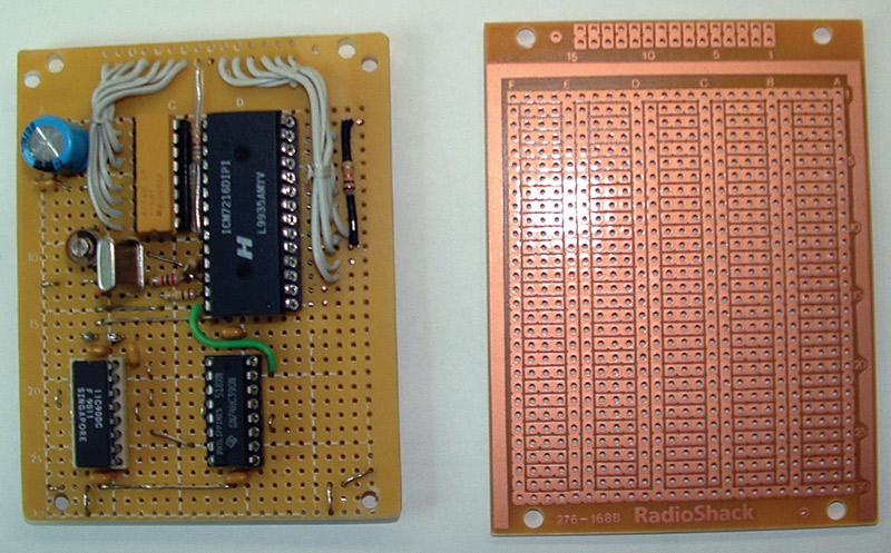
FIGURE 3.
One trace has to be cut and several others jumpered on the power supply rails. Also, there is a small amount of foil grinding to do where the ICM7216D is located. I will be omitting a lot of details from here on out due to size restrictions for publication, but as I have done in past articles, there will be an email packet with additional pictures and construction information I can provide on request for those who are interested. You can also check for updates in the downloads.
Once you modify the circuit board, you can mount the IC sockets (I used sockets for each chip). The pins on the right side of the 7216 socket will end up in the ground-out foil area; they require a series of short jumpers from the pins to the respective solder pads adjoining the socket. You might not need the resistor pack RP1 socket for your LED display. However, it is so cheap and when dropped in place mates up perfectly with the segment outputs. In fact, it drops onto the same solder pads as the 7216 so there are not even any connecting wires needed.
The LED displays that appear in the Parts List are high-efficiency red. These displays emit a lot of light using very little current drive; the resistor pack was necessary to limit their current draw. Using an assortment of resistor packs, it was easy to determine the degree of brightness I wanted just by swapping them out. The value I chose was 680 ohms; I could have increased this to 1K ohm and achieved sufficient brightness. Even if your display needed more drive than that, it's still a good idea to have some limiting resistance, if for no other reason than to help extend the life of the 7216.
The resistor packs contain eight resistors and require a 16 DIP socket. Seven of these resistors are used in a series with the seven-segment outputs, but the one in the middle just happens to line up where the 7216 V+ pin is located. This resistor was left unterminated on the other end. You could do a lot of grinding in this area and free it up for the decimal output segment, but I found it easier to just run that output directly to the display through its own 680 ohm resistor.
All of the 7216 digit and segment lines were run to the front of the board and terminated at the inboard row of holes. When the display assembly is complete and wired, those leads will be connected to the mating outboard row of holes. This configuration makes assembly simple and straightforward. The 7216 series of chips can perform a lot of functions because the multiplexed digit output pulses it uses act as enabling triggers for various purposes.
We will use two of these functions in this design: the range (gate period) and external decimal point control. To enable the external decimal point feature, you must make a connection from the control pin (1) to the D3 output pin (4) through a 10K resistor. My displayed decimal point is on LED digit 4; I had to run a wire from the decimal-in pin (13) to D4 (6) on the chip. I selected a 0.1 second gate time; activating this function required a connection from range (14) to D2 (5) through a 10K resistor. The 10K resistors suppress stray pickup on these lines. A 100K resistor to ground from pin 27 disables the hold function. The only remaining step in the frequency counter retrofit process is to wire the oscillator.
Connect the oscillator as shown. The trim cap C6 can be made up of any combination of fixed and variable capacitance, as long as you end up with about 30-35 pF total with the trimmer at mid-range. (Note: The crystal shown in Figure 3 is not the one listed in the Parts List. It was replaced after the photo shoot was completed. The replacement has better frequency stability and aging characteristics than the original.)
All crystal resonant frequencies will change somewhat due to aging. The order of acceleration of this phenomenon is as follows:
- Unavoidable chemical impurities from production, even when just sitting on the shelf; very minute.
- Active operation; this one ages at 3 PPM per year — a better than average rate.
- High ambient temperature or over-driving, maybe 10-15 PPM per year.
Typically, after the first year of operation, the aging rate slows down significantly. The added trimmer makes quick work of putting it back on frequency when required. As for the three bypass capacitors coming off of V+ (pin 18), they were placed as follows: 0.01 µF at the pin 1 end of the chip; 0.1 µF at the pin 14 end of the chip; and 470 µF at the incoming V+ connection point. These drop in conveniently right over the power supply rails in each location.
The prescaler is made up of two chips: an 11C90 and a 74HC390. The 11C90 is the first stage in line to receive the clock signal (F in) and is configured to divide by 10. This chip is a member of the ECL (Emitter Coupled Logic) family. The key to its high speed operation is that it never enters into saturation or cutoff in its logic level swings, which are approximately 800 mVpp. Operating in this mode, PN junctions can perform extremely fast switching, and this particular one is rated at over 800 MHz.
The input is capacitively coupled so that it can be tied to an internal DC bias supply. This sets its operating point to its most sensitive region and increases its sensitivity to approximately 65 mV rms. This chip also has an ECL-to-TTL translator built into its output, so it will have no problem driving succeeding TTL or CMOS chips that follow it.
Of particular interest is its ability to operate on incoming signals at low frequencies and with slow rise times. Most ECL chips do not operate properly below 10 MHz due to the slower rise times incurred. The 74HC390 is a dual bi-quinary divider, and only half the input is used and configured as an x10 divider. The clock pulse from its output drives the input to the 7216 (pin 28) and is exactly the input frequency divided by 100.
The circuitry for the entire prescaler is so straightforward and simple, it requires no further information. For the most part, it does not require any components, and it only needs point-to-point wiring. However, its construction requires further discussion.
Each stage needs very short leads and a good ground system around it for good individual stage neutralization. This is where the RS circuit board shines with its power supply rails running directly under the chip as it facilitates tight wiring and bypassing.
Place the bypass capacitors for each stage (refer back to Figure 2) as follows: 11C90 - C2 at the input end of chip (15), C3 at the output end of chip (11); 74HC390 - C4 at the input end of chip (15), C5 at the output end of chip (9). As previously mentioned, these caps drop in conveniently right over the power rails.
Note: The 74HC390 shows its output taken off pin 7 (see Figure 3); this output should actually come off pin 9 as shown in the schematic (again, this change was made after the photo shoot). I decided to use the other half of this divider to keep connecting leads shorter. I used RG-174 cable for the clock lead (Fin) and attached it right at the capacitive coupled input to the 11C90. The other end is terminated with a standard RCA phono plug. The incoming power leads attach directly to C10.
I cut a piece of perfboard to the required size and super glued the LED digits to it. Then, I attached some small L brackets to it so that I could install it to the circuit board later.
Wire up the displays and leave two inch leads extending from it. Lay the RS board face up and the display board face down in front of it. Connect the leads to their proper locations on the RS board; then, fold it up and attach it to the RS board using the pre-installed brackets. The screws used here must be long enough to run completely through the brackets, RS board, spacers, and metal housing which you will then secure with nuts. Secure the opposite end of the board in a similar way. Obviously, this will require some prior machining. (The e-packet will contain all the details.) The completed circuit/display board is shown in Figure 4.
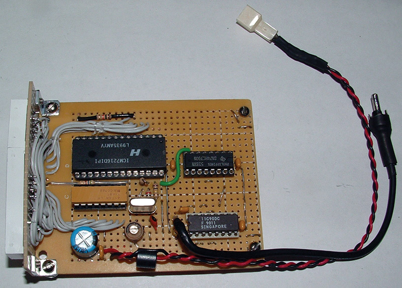
FIGURE 4.
The housing for it measures 3" wide x 3-7/8" deep x 1" high, and it’s shown in Figure 5. At this point, the counter is retrofitted and is ready for testing and final installation.
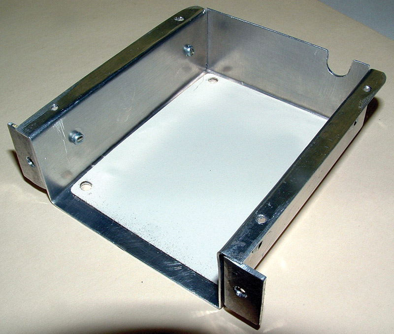
FIGURE 5.
Closing Notes
The retrofit just described was a joy to build because it was so simple! I know some readers might say this could be done just as easily with a microcontroller, but I’m not so sure I would agree. Having seen many designs on the Internet, I would not argue that it looks simple, but I see a lot missing such as prescalers, function controls, and actual display circuits in lieu of a laptop.
As one who despises pages of software and loves through-hole construction, this chip is a winner for me. The support circuitry needed is almost next to nothing, and the features that can be added are effortless due to the simple built-in connections to achieve such. This chip has full capability for eight-digit displays (either LED or LCD), numerous modes of operation, leading zero blanking, display testing, and the list goes on.
As a member of the CMOS family of chips, its current draw is negligible. The design just covered requires 100 mA max current. Breaking it down, that’s 14 mA for the display; 2 mA for the crystal oscillator; 1 or 2 mA for the chip itself; and a whopping 83 mA for the prescaler (the price you pay for wide band/high speed operation).
If you opt to build the retrofit but can’t 'shoe horn' it into existing equipment, you could put the 5V regulator chip on board and power it from a wall transformer. Devise some quick disconnect mount for attachment; even Velcro™ would work. Want to take it to the max (e.g., a stand-alone universal counter)? Use the full eight-digit capability and either the A or B version (depending on the common connection of the display digits), all the bells and whistles, and an internal power supply. In either case, the supplies will need +5V at 100 mA or more, depending on how many extra features you want.
The Tamura transformer 3FS-316 and a 7805 regulator would work perfectly here. It is small, affordable, and available through the usual distributors. For use in low frequency operation with an upper limit of 10 MHz, you can bypass the prescaler and go direct; the resolution can be set for 1 Hz.
For counting operations upwards of 1 GHz (probably closer to 800 MHz) with an eight-segment display, the resolution will be 100 Hz, still using the divide by 100 prescaler. I tested the prescaler shown in Figure 2 across a wide range of frequencies, and it performed flawlessly to 500 MHz with even sensitivity across that range (65 mV rms). However, at 525 MHz, it started to sputter. This was due to the 74HC390 reaching its upper frequency limit of 50+ MHz. No problem for the described retro counter, but if you need to push it higher a modification is needed.
The insertion of a 74VHC74 bistable between the 11C90 and the 74HC390 will increase the prescaler capability to 1 GHz. This chip is of the 74VHC family — a very high speed dual D type flip-flop; only one side is used. It will handle well above 150 MHz clock signals, and by connecting this in 'toggle' mode, operation will cut the clock signal in half at this point. This, in turn, will supply the 74HC390 with a lower speed that it can handle with ease. The 74HC390 will have to be reconfigured for quinary operation (divide by 5), which is a very easy task; this will preserve the overall divide by 100 of the prescaler.
I would recommend a preamp on the input of maybe 10X gain, and that the entire prescaler be constructed on single-sided copper board due to its higher frequency range. Of course, there are myriad prescalers out there that could be used, but a lot of them have binary division ratios which will require some added circuitry to end up with the correct division ratio.
If you decide to build up this counter, make sure you download the datasheets for all the chips before you even start. The 7216 has all suffix versions on the same datasheet. Read through this at least once, if for no other reason than just to get a better understanding of what you are working with. To me, the datasheets seemed a bit sketchy and had a few typos. I actually had to read it twice before I had an adequate understanding of it, but all in all gained very good info. The other two datasheets are pretty straightforward. Also worth mentioning here is that the Intersil 72xx series has many related counter chips that have options for digital programing, etc., that might be of interest to you.
I hope I have covered all the bases here without any holes in my explanation, but the e-packet will fill in any missing gaps. One thing I do know for sure — and because of the utter simplicity of these chips — I will probably be adding a lot of counters to existing equipment in the coming year. NV
PARTS LIST
| ITEM |
DESCRIPTION |
PART # |
SOURCE |
| All resistors are 1/4 watt 5% carbon film. |
| RESISTORS |
| R1* |
680 |
|
|
| R2 |
22 meg |
|
|
| R3 |
100 |
|
|
| R4 |
100K |
|
|
| R5 |
10K |
|
|
| R6 |
10K |
|
|
| RP1* |
680 x 8 |
|
|
| CAPACITORS |
| C1, C3, C5, C8 |
0.1 µF |
|
|
| C2 |
0.001 µF |
|
|
| C4, C9 |
0.01 µF |
|
|
| C6 |
10-50 pF variable |
|
|
| C7 |
36 pF |
|
|
| C10 |
470 µF |
|
|
| CRYSTAL |
| 10.0000 MHz |
|
|
|
| FERRITE BEAD |
| FB-1 |
J. W. Miller |
|
|
| INTEGRATED CIRCUITS |
| IC1 |
|
11C90 |
eBay |
| IC2 |
|
74HC390 |
Mouser |
| IC3 |
|
ICM7216D |
eBay |
| DISPLAY |
| Two-digit |
LITEON |
LTD-4708JR |
Mouser |
| Four-digit |
LITEON |
LTC-4727JR |
Mouser |
| CIRCUIT BOARD |
| * Depends on display drive current desired. |
| Datasheets for all ICs are readily available on the Internet. |

