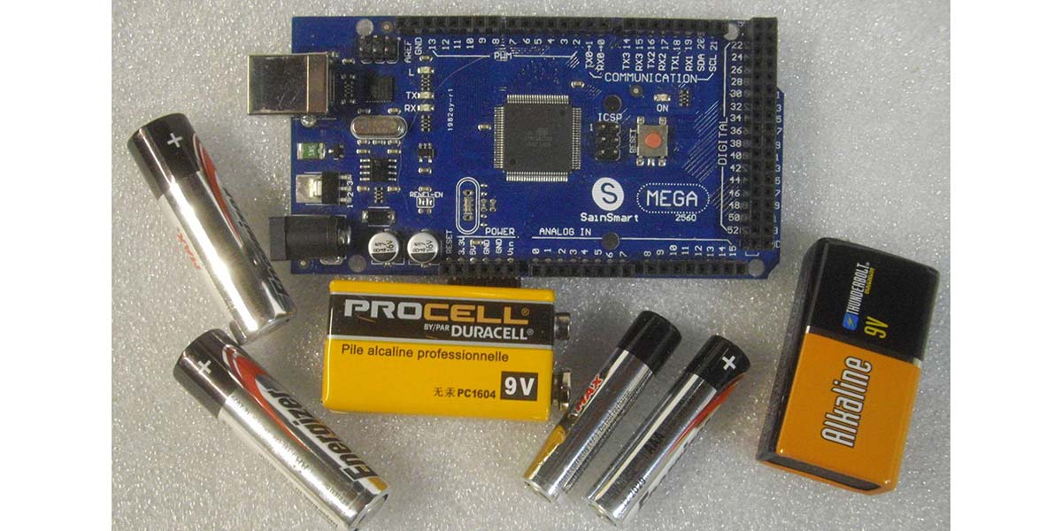
In Part 1 of this series, we discussed measuring project power needs, battery options, and ways to define and estimate battery service-hour life. While it’s no surprise that bigger batteries provide longer service life, Part 2 explores some ways to more efficiently use battery power to maximize battery life.
Modern Power Management
In this day and age, most or our electronics are smart enough to automatically ‘sleep’ or completely power-down after a preset period of inactivity. For example, my cell phone saves power by turning the screen off 30 seconds or so after I stop using it. My Fitbit similarly goes blank after a quick display of step-count. Even a cheap $15 component test and ID box I bought off eBay has auto power-down 20 seconds after showing the test results.
So, I decided to see if I could come up with a simple way to add power-down functionality into my DIY designs. I also looked at ways to improve the overall efficiency of battery powered projects.
Overview
To provide effective power-down capability, I first focused on developing a power control circuit to go between the battery and the power input of an Arduino style microcontroller that seems to frequently appear at the heart of many of my projects. A block diagram of my thinking is shown in Figure 1.
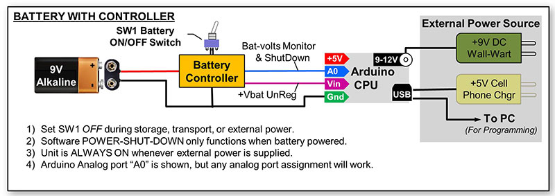
Figure 1. Block diagram of the battery controller.
Functional Requirements
When first turned on, the battery controller should immediately fully power-up the project. However, once its work is done, the battery controller must provide a hook that allows the project CPU to power itself down. In this way, the CPU can initiate a battery saving ‘power-off’ action for the cost of a few lines of code.
In particular, I wanted to stop battery waste resulting from excessive “idle periods” and user “walk-away” events. I also wanted to provide a battery voltage sense point that could be used to report battery status with an onscreen battery gauge or “low battery” blinking LED.
The Battery Controller Circuit
Figure 2 shows the battery power controller circuit I came up with.
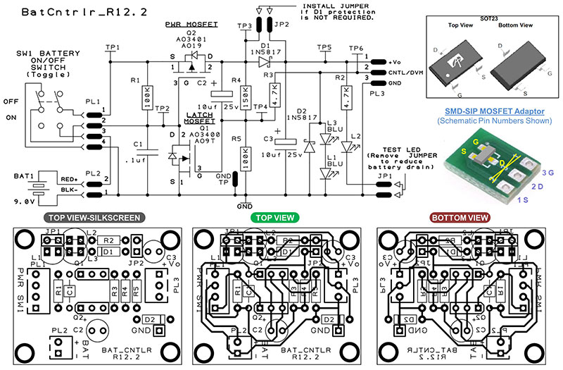
Figure 2. Battery controller schematic and prototype PCB Layout.
I used a hard mechanical ON-OFF DPDT toggle switch to ensure complete battery isolation during device transport and storage, yet provide an easy and familiar operator ON-OFF control. It’s seen that power MOSFET transistor Q2 is basically all that stands between the battery and the CPU power input.
The battery controller delivers power to the CPU and ‘talks to the micro’ through a single CPU I/O pin that provides both a battery voltage measurement point to the CPU, as well as a route to receive a software driven power-off signal from the CPU. Although I developed and first used this battery controller for a recent Arduino Mega based RJ45 cable tester project (a future article), the base circuit and ideas presented here should work well with almost any other micro board as well.
How the Battery Controller Works
In reviewing the schematic, Q2 (the main power MOSFET switch) is “turned off” whenever its gate (TP2) voltage is high (about the same voltage as its source-pin voltage, TP1). Conversely, Q2 goes into full conduction (“turns on”) whenever its gate voltage (TP2) is low (a few volts or more below the source pin voltage TP1). Although many P-channel MOSFETs can work well here, the AO3401 P-channel power MOSFET I used is a cheap (Amazon, $.09 ea., 100 pieces for $9), four amp device with a low Gate Threshold Voltage (VGS(th)=1.3V), and low Drain-Source On-Resistance (RDS(ON)<50 mohms).
The companion AO3400 N-channel MOSFET features similar specs, is equally inexpensive, and worked well in this circuit. Furthermore, its low Gate Threshold Voltage makes it easy to drive from any 3.3V or 5V microprocessor I/O pin, so it makes a good part to have on-hand.
Turning Power On
The off position of double-pole-double-throw (DPDT) switch SW1 provides complete battery isolation during storage and transport. When in the off position, the connection to the positive terminal of the battery is interrupted, providing complete battery isolation and zero external current draw. Also, when off, C1 is shorted to ground to ensure it’s fully discharged. As soon as SW1 is flipped on, +9 VDC instantly appears at the source of Q2 (TP1).
Since the gate of Q2 starts out low (C1 discharged), Q1 immediately begins conducting and delivers 9V to the +Vo output pin of the battery controller for use by the CPU and the rest of the project. The combination of C2 and resistor divider R4-R5 connected to the gate of Q1 (TP4) immediately biases Q2 into conduction which then holds C1 and the gate of Q2 at ground potential. This keeps Q2 conducting, project power on, and everyone is happy!
In this way, power is latched on. In the absence of any other actions, power will remain on forever or until the battery runs out, whichever comes first!
Reading Battery Voltage
With the junction of voltage divider R4-R5 (T4) connected to a CPU input pin (TP6) through R3, we can read the battery voltage. By using an analog A/D capable I/O pin, the microprocessor can easily measure and monitor battery voltage. The R4-R5 divider reduces the 9V maximum battery voltage to about 3.6V, keeping it below the maximum Arduino A/D input voltage of 4.1 volts. You can tweak the values of R4 and R5 as needed for different maximum CPU input voltage values and/or different maximum battery voltage levels.
In Arduino C++, reading the battery voltage is easily accomplished as seen in Figure 3.
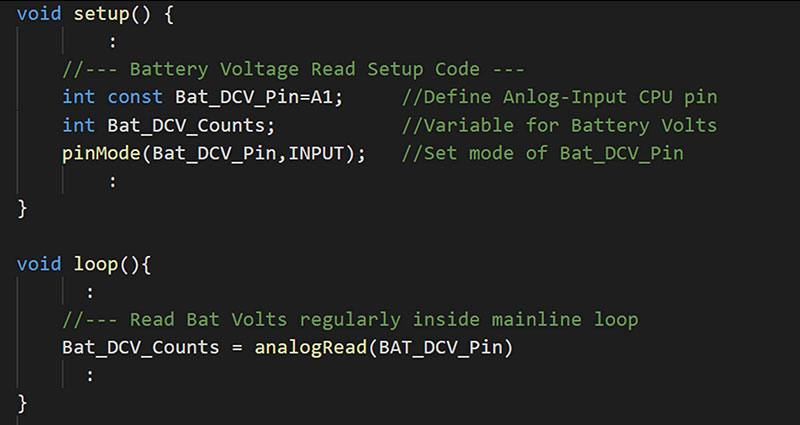
Figure 3. Code snippet for reading battery voltage.
Using your DVM to measure the actual battery voltage, a calibration factor can be derived that will enable you to show an actual voltage value display if that is appropriate for your project. Percentages, full-to-empty battery gauges, or time-until-battery-exhausted readouts are also possible once you learn the battery consumption profile (voltage vs. run-time) for your project. A fancy battery status display like that shown in Figure 4 is easy if your project already sports a graphics display.

Figure 4. Battery status display.
In this example, “Off:107” is telling the user that auto power-down will occur in 107 seconds. Of course, a CPU driven “Bat OK LED” and/or flashing “Low-Bat LED” is an even simpler option to keep the operator alert to battery conditions.
Turning Power Off
Of course, the operator can toggle SW1 to off at any time. However, as discussed, even though the manual power switch remains on, the main feature I was trying to implement was a way for the CPU to power-down the system and turn itself off. As shown in Figure 5, this is accomplished in software by changing the Bat_DCV_Pin CPU-I/O port from INPUT to OUTPUT mode.

Figure 5. Code snippet for software power-down.
Then, the CPU can actually drive the gate of latching N-MOSFET Q1 (TP4) low (~0V) causing a power-down event.
Once Q1 stops conducting, C1 quickly charges up through R1; once the voltage level of C1 is high enough, Q2 is cut off, stops conducting, and the battery controller output voltage goes to zero. Note that the delay(..) command following the digitalWrite(..) in Figure 5 just gives the CPU something benign to do while waiting for the power to actually drop out.
Reactivation After Software Shutdown
As noted, once the battery controller circuit has been electronically powered down by the CPU code, C1 charges up and holds power transistor Q2 permanently off. To reactivate power, the operator just needs to cycle the power toggle switch to off and then back to on. This action will discharge C1, reset the whole power control cycle, and then turn on the power controller output.
Leakage Current After a Software Shutdown
The power MOSFET Q2 has very low leakage current when off. I admit that taking low current measurements (< 1 ma) are difficult and confess that my DVM only reports down to the nearest 0.1 µA. However, even in its most sensitive range, I couldn’t detect any current flow through Q1 after a software power-off event (SW1 = ON). While better instrumentation (perhaps a new project?) would no doubt see some off leakage current, my tests suggest it’s likely to be in the sub-micro amp realm.
In any event, toggling SW1 to off for storage and transport will prevent even those last few electrons from sneaking out of the battery. Note, however, that batteries aren’t perfect. That is, even when fully disconnected, batteries exhibit some self-discharge due to current leakage paths within the battery itself.
Battery manufacturers specify self-discharge indirectly as a “shelf life” value. For most alkaline batteries, the shelf life is typically rated in the five to 10 year range. What this means in practical terms is that older batteries that are into the middle or later stages of their rated shelf life will be partially depleted and therefore provide shortened project service life.
Battery Protection Circuits
Schottky diode D1 in the schematic of Figure 2 is provided to prevent reverse current flow from the CPU board back into the battery should you simultaneously supply power to your project from BOTH the battery (SW1 = ON) and an external AC wall wart power pack. With D2 in the circuit (JP1 not installed!), reverse current flow which could cause battery heating is prevented.
While this provides useful protection, it unfortunately places an additional Schottky diode voltage drop (.2 to .3 VDC) in series with the battery output, reducing available battery life a smidge. If you “promise to never dual power your project,” you can replace D1 with a wire (or install jumper JP1) to maximize battery service life for your project.
CPU Port Protection Circuits
In addition to battery protection, we also need to protect the microprocessor I/O port from voltage overloads. During every power-up sequence, a positive-going nine volt spike passes through C2 and, in turn, tries to attack the connected I/O pin of our microprocessor. This pulse will actually serve to drive Q1 into conduction and helps provide the needed “power on” latch functionality. While this is a good thing for Q1 and Q2, this 9V pulse will pass through R3 and exceed the maximum input voltage limit of the CPU I/O pin. To prevent CPU damage, it’s common practice to simply place a 5V Zener diode across the I/O pin to ground to limit (a.k.a., “clamp”) the voltage reaching the I/O pin to 5V or less.
While this technique works well, I didn’t have any 5V Zener diodes on hand. So instead, I just stacked two blue LEDs on top of each other (L1 and L3) to make a 5V Zener diode substitute.
Since each forward biased blue LED behaves like a 2.5V Zener diode, two in series creates a five volt clamp to protect the I/O pin. In fact, every time you toggle the power switch from off to on, you’ll actually see these two LEDs briefly blink on as they conduct and clamp the overvoltage power-up pulse.
As soon as C2 charges up and things settle out, the voltage across the LEDs falls below 4.0V, the LEDs extinguish, and no longer load down the battery. You can use a single 5V Zener diode or a pair of blue colored LEDs as I have done to create this protective voltage clamp. However, don’t substitute red or green LEDs as their forward voltage drop is different from blue versions, reducing the voltage clamp point.
If the clamp level is too low, it will interfere with the analog A/D battery voltage reading you’ll see and therefore compromise the accuracy of your battery monitor.
While LED L1 and L3 keep positive overload voltages at bay, Schottky diode D2 protects the I/O pin from negative below ground voltage excursions.
While on, capacitor C2 will stabilize at about +5 VDC when powered by a fresh 9V battery. When power is turned off, the +Vo rail quickly drops to 0V. This also drives the positive side of C2 towards ground.
When this happens, the charge stored in C2 is “pushed below ground” and momentarily appears as a negative voltage source of nearly -5 VDC when measured with respect to circuit ground. D2 is in place right across the I/O pin to clamp this negative voltage excursion to less than -0.4 volts, thus preventing I/O port negative overvoltage damage.
Putting the Battery Controller to Work
The interconnection block diagram back in Figure 1 shows how the battery controller circuit fits between a 9V battery and the voltage “Vin” pin of an Arduino CPU. Recall that Vin is the unregulated power input connection to an Arduino.
As described, the DVM_CNTL wire from the controller should be connected to the analog I/O pin of your choice, so that battery voltage can be read and power-down actions can be triggered by your program.
Building the Battery Power Controller
The detailed bill of materials for the power controller is shown in the Parts List. Although I list 1% resistors there, the values are not critical and wider tolerance parts should also work fine. For the cabling to/from the controller board, I favor JST-XH headers. I’ve been using these connectors for some time and like that they are spaced on a .1 in grid, yet are shrouded and keyed to prevent “backwards plug-in” errors. Having said this, other wiring schemes including hard soldered ‘flying leads’ are also a viable build choice.
Although I designed a single-sided PCB (printed circuit board) layout for the controller circuitry, I actually built my version on a small 1.2 x 1.5 in piece of .1 x .1 in grid protoboard (Figure 6).
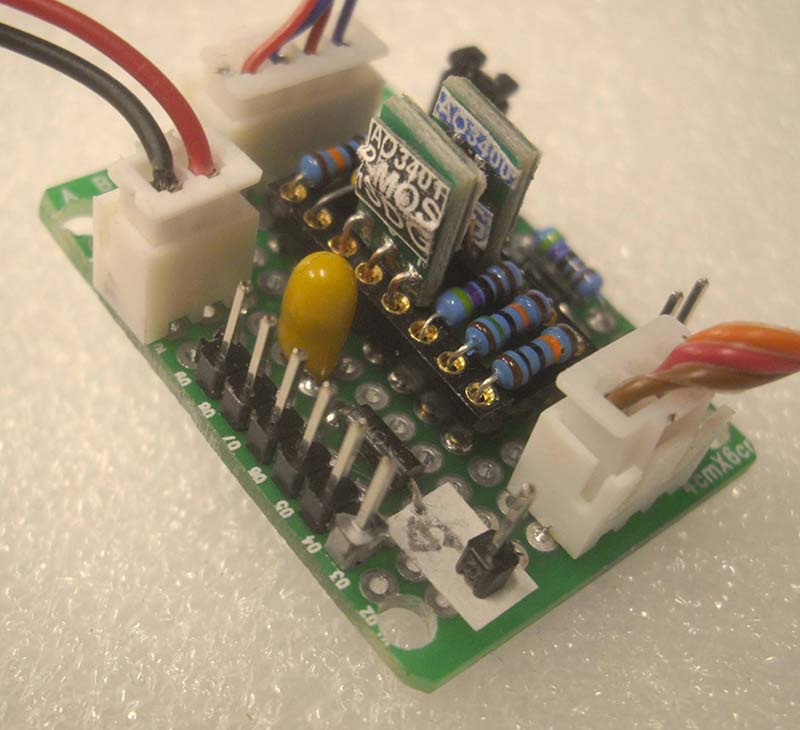
Figure 6. My prototype battery controller.
I used a single 16-pin DIP socket to hold the MOSFETs, C1, and most of the resistors. This allowed me to easily swap in different values during development, and might be handy for your build should you want to fine-tune the design to specific project needs.
Once I soldered the socket, interconnect headers, and miscellaneous discrete components to the protoboard, I used 30 ga wire (lengths of wire-wrap wire) to make all the point-to-point connections on the back side of the board, more or less mimicking the copper traces as they appear on the PCB layout.
Note that I also added a ground pin and a six-pin SIP header, which I wired to test points TP1-TP6 on the schematic. This gave me easy meter and scope access during the final test and checkout.
Working with SO23 SMD MOSFETs
I grew up in the ‘through-hole circuit board’ era and found working with the small SO23 MOSFET surface-mount devices (SMD) to be a challenge — both for my eyes as well as manual dexterity! I solved this problem by using low-cost PCB adapters (Figure 7) that convert the SMD transistors into three-pin SIP devices.
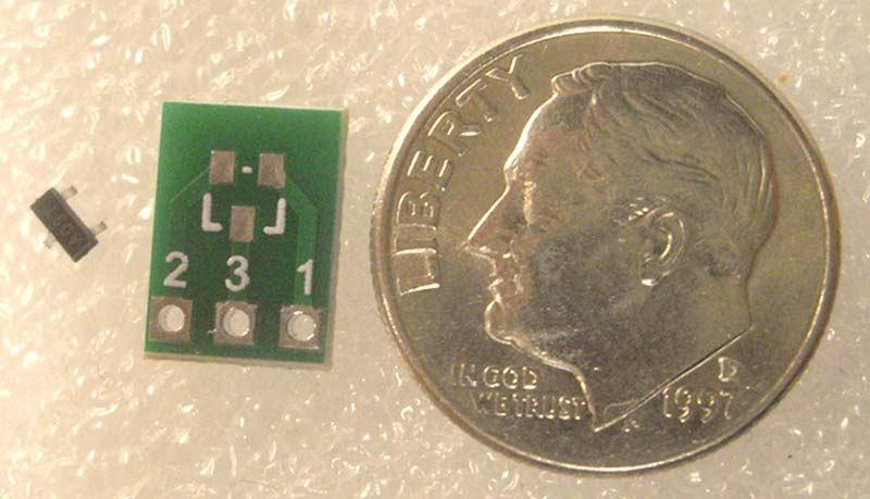
Figure 7. SMD to SIP adapter.
These adapter circuit boards can be found at both Amazon and eBay for about $.20 each (50 for ~$10). With the aid of a magnifying headband, a small tip iron, and a shot of brandy (to stabilize my hands!), I was able to maneuver the SO23 parts onto the adapter pads and solder them in place. The brandy also helped me cope with the loss of a few SMD parts that mysteriously flew away from me and disappeared during assembly!
Soldering short lengths of small gauge solid wire or a three-pin male SIP header onto the adapter completes the SMD to SIP transformation. Once converted, these transistors can be easily plugged into a solderless breadboard for experimenting, and in my case, installed vertically into the IC socket I used for my protoboard build.
If you go this route, be sure to carefully study the pinout of the adapter PCB, SOT23 part, and your circuit board wiring.
There’s lots of ways to goof this up and it doesn’t help that the numeric labeling on the adapter board didn’t follow the normal SIP-style sequential pin numbering scheme, which, by the way, I used in the schematic and PCB layout.
Increasing Efficiency — Adding a Step-Down Switching Regulator Module
With my project code updated for reading battery voltages and implementing software shutdowns, I was very pleased with the results. However, it occurred to me that I could further extend battery life by using a more efficient battery-to-5V conversion scheme. By inserting a step-down switching voltage regulator (a.k.a., buck regulator module) between the battery controller circuit and the microprocessor, the energy wasted as heat in the onboard linear voltage regulator could be eliminated.
A quick search on Amazon and eBay revealed the availability of some very inexpensive buck regulator modules (10 for $8, actually; less than a buck!). Buck regulators use switching power supply ICs to convert the unregulated input voltage into a regulated output voltage. Just like linear voltage regulators, the input voltage to a buck regulator must always exceed the target output voltage by one to two volts.
Unlike linear regulators, however, buck regulators don’t waste much energy as heat. As such, buck regulators achieve much higher efficiencies (typically 90% or more!). Figure 8 shows a photo of one of my “10 for $8” regulator modules.
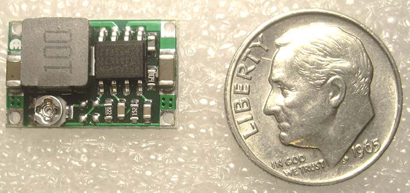
Figure 8. Mini buck regulator.
The battery controller actually works quite well in concert with a buck regulator. The interconnection scheme for this higher efficiency configuration is shown in Figure 9.
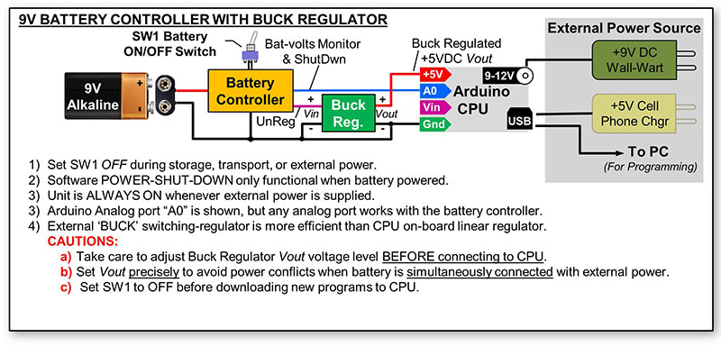
Figure 9. Battery controller with a buck regulator.
Here, we feed the unregulated battery voltage output from the battery controller to the input side of the buck regulator module. The output from the buck regulator is then connected directly to the +5 VDC rail of the microprocessor board, avoiding the onboard linear regulator all together.
CAUTION: The buck regulators I used feature a small potentiometer to set their output voltage. One needs to set the output voltage to the correct value needed by your CPU (usually 5.0V or 3.3V) BEFORE connecting the buck regulator output to your CPU board. You risk killing your CPU in a fatal overvoltage event if the output voltage is not properly pre-set ahead of time to match the voltage requirements of your CPU/project.
Why not use the ‘enable’ pin of the buck regulator IC to turn power on and off? Yes, the readily available regulator modules based on MP1485, MP1594, MP2307, and similar switching regulator ICs do have a power supply enable pin (a.k.a., EN). When left disconnected (or pulled up), the regulator starts up immediately upon receiving an input voltage and delivers a regulated output voltage. When the EN pin is driven low (typically < 2 VDC), the regulator shuts down. Might this eliminate the need for the power MOSFET on the battery controller?
Well, I tested this approach and found that even though the regulated output voltage does turn off when the EN pin is low, the regulator IC chip itself still continued to consume 15-30 µA even when disabled. I felt this was way too much off-state battery drain and abandoned using the EN pin as the primary power-down switch.
Buck Regulator Battery Life Results
By following the battery power controller with a buck regulator module, the ability to monitor the raw battery voltage and perform code driven power-downs are fully preserved, while battery-to-CPU regulation efficiency is greatly improved. So, what does it get you?
I ran another battery life test on my RJ45 cable tester project to find out. Figure 10 shows both my prior linear-regulator test runs (described in detail in Part 1), along with the new 5V buck regulator version.
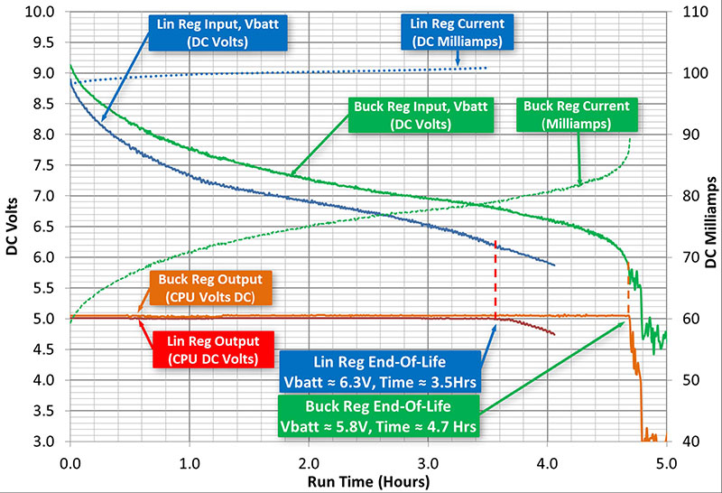
Figure 10. Using a buck regulator to increase battery life.
Note that throughout the battery service life, the Arduino onboard linear regulator scheme appeared to act like a constant ~100 mA load to the battery. The buck regulator version, however, varied its current draw from 60 mA to 90 mA as the battery energy was consumed.
Even though the current needed by the buck regulator changed throughout the battery life, the buck regulator scheme was still more efficient and increased the overall service life by more than 30%. For my RJ45 cable tester, the previous 3.5 hour service life realized with linear regulators increased to more than 4.6 hours with the buck regulator approach.
Hey, What About Rechargeable Batteries?
I focused on single-use alkaline batteries for these articles as rechargeable batteries require more specialized care and feeding. For example, when using lithium-ion batteries, it’s important to prevent both overcharge and overdischarge of the battery as either case leads to permanent battery damage and premature battery failure.
Also, strict recharging and load balancing protocols in multi-battery parallel or serial configurations need extra attention. For these reasons, I’m sticking with single-use alkaline batteries for now and will leave rechargeable batteries for another time.
A Few Other Power Savings Ideas
When thinking about your battery powered designs, don’t forget some of the easy wins. Dimming LEDs and LCD backlights, for example, isn’t hard to do for most microprocessors (think PWM). Also, check out the special low-power CPU modes (sleep) that your micro supports to further save power when possible.
What if Your Project Isn’t Microprocessor Based?
While I more or less assumed all projects should use microprocessors (a bit narrow minded, don’t you think?), understand that the battery controller presented here can easily auto power-down your project when driven by a NE555 timer or other non-CPU project signal.
For pushbutton on-off controls, a normally-open momentary pushbutton connected from PL1-pin 2 to ground should work as a start button (SW1 must already be set to on).
A normally-open momentary pushbutton from PL3-pin 2 to ground could become a simple stop button. The battery controller circuit presented here is fairly straightforward, so feel free to experiment and adapt the design to better fit into your needs.
Wrap-Up
Understanding project power requirements, battery capacity, and service hour charts helped transform my RJ45 cable tester into a battery-powered portable instrument.
Furthermore, the battery power controller presented here helps me stay informed of battery status as well as provides a much needed auto-off function to overcome my absent minded walk away tendencies!
I hope these ideas can help you integrate battery monitoring and “auto-off” functionality into your next portable project. Best of luck and happy experimenting! NV
REFERENCES
Alpha & Omega Semiconductor, AO3401 P-MOSFET Datasheet: http://www.aosmd.com/pdfs/datasheet/AO3401.pdf
Alpha & Omega Semiconductor, AO3400 N-MOSFET Datasheet: http://www.aosmd.com/res/data_sheets/AO3400.pdf
Amazon Mini Buck Regulator Search Term: “Mini 360 3A DC-DC Voltage Step Down Power Converter”eBay Mini Buck Regulator Search Term: “mini buck regulator“
Amazon/eBay Proto-PCB Search Term: “proto board pcb”
Amazon/eBay SMD to SIP Adapter Search Term: “SMD SOT23-3 to DIP SIP3 Adapter PCB”
Downloads
Adventures in Battery-Land Parts List

