The most often used trouble indicator in a circuit is the ubiquitous LED. Unfortunately, we don’t always have eyes on our equipment to see when problems arise. So, what should you do?
Adding an audible alarm is probably the easiest option. There are several variations. We’ll be discussing a few of them in this article, varying from the easy-to-build to the slightly more complex.
The circuit you choose for your trouble alarm can be one standard type (whichever circuit you prefer or find easiest to build) or a combination of different alarms to let you know which project on your test bench is in trouble based on the alarm you’re hearing. The simplest audible trouble alarm is probably the buzzer. These come in different types and forms based on a user’s requirements and are easy to use: Hook up the ground and +V wires coming out of them, and they’ll sound off.
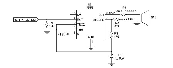
The next step up is shown in Schematic 1.

Schematic 1.
When a circuit (or other project) goes into trouble mode, let’s assume we have a logic “1” (+V) signal available that stays in that state as long as a problem exists; when the problem no longer exists, the alert signal returns to a logic “0” (ground). This logic is fed into the enable input of a 555 timer (U1) which then, in turn, oscillates at a rate (with the values shown) at 1 kHz, which is fed into the speaker via R4 (more on the speaker parameters later).
The next possibility is an alternating on/off alarm shown in Schematic 2.

Schematic 2.
When U1 receives a positive signal on pin 4, the 555 timer will oscillate at 1 Hz. This is then fed to U2 which oscillates at 1 kHz, feeding a speaker that gives us an audible alarm at an on/off rate of 1 Hz (sounds a bit like a car horn going “beep!” pause “beep!” pause, etc.). This will continue as long as an alarm condition exists.
A third option is an alarm that has two alternating tones. Whether you just want to get fancy or differentiate this idea from other audible alarms present on your workbench, this will provide the next step in designing a unique alarm (Schematic 3).

Notes:
- The value for R5 & R9 depends on two things: the maximum power rating of the speakers and the 150 mA maximum ratings of U2 & U3. It also controls the volume. Be sure max values are not exceeded!
- A dual timer (556) may be substituted for any two single 555s; it depends on the circuit board layout preferences of the builder. Keep in mind if one of two should fail, replacing a 556 will waste half of the IC! Also keep in mind that when buying parts — especially if the builder uses a lot of timers — buying a higher quantity of 555s may qualify for bulk purchase rates.
- A +12V supply is shown for convenience (most ham stations have this available to power mobile radios). If a +5V computer power supply is available, this should work equally as well.
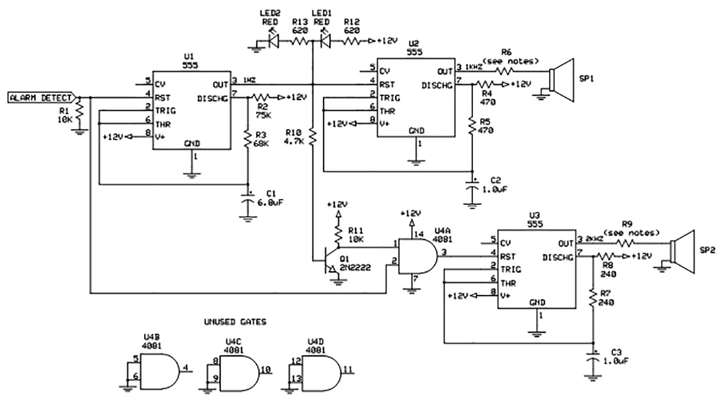
Schematic 3.
U2 and U3 here operate the same way they do in Schematic 1. U3 is wired to operate at a different tone (in this case, 2 kHz) and to turn on when U2 turns off (and vice-versa). Here’s how it works: When U2 loses the enable signal (logic “1” or +V) from U1, U3 is enabled (and again vice-versa) through Q1 (wired as an inverter).
For U3 to run, we must also determine if the output of U1 went low because an alarm condition no longer exists, or we’re between positive pulses. To do that, a dual-input AND gate is used. If an alarm condition exists (indicated by a positive signal on the “alarm detect” input) and U1 went low, U3 will oscillate.
Wiring the Speaker
The 555 timer can source or sink up to 150 mA. Even if we have a speaker available that can handle this power level (1.8 watts with a 12V supply), we want to make sure that we don’t exceed the power that the 555 can deliver (or sink).
Since the speaker isn’t important — any salvaged speakers from our junk box will be fine — we may also need to lower the power being sourced/sunk by the 555 so we don’t over-drive the speaker. That’s the purpose of the resistor located in series with the speaker (calculated as follows: Presistor = Pmax-IC – Pspeaker).
Since we’re at about two watts (minus what the speaker uses), make sure you use a resistor (or combination of resistors) that can handle the power dissipation. This resistor can also be used as a volume control; if the builder wants to vary the speaker volume, for best results use an audio taper (not linear taper) potentiometer, also being careful to allow for power handling capability.
s an additional indication, a visual aid in the form of two LEDs shown in Schematic 3 can be added to U1 in Schematic 2 as well. The LEDs are not mandatory and don’t affect the operation of the timers; they’re just an option for those who’d like to have a visual aid as well. (A visual aid not only acts as an additional source of information for the user, but also adds a “wow” factor when visitors see some visual action going on.)
Status LEDs (including one across the circuit’s power supply line) add an indication of what the circuit’s doing in case troubleshooting is necessary.
The frequency of the 555 timers can easily be changed to suit the preferences of the builder; the frequencies shown here are not engraved in stone. The main thing to keep an eye on is to choose timing resistors to be close to each other in value so that the duty cycle of the 555 is at least close to symmetrical. To change the operating frequency of the timers, use the formula:

There’s no need to be concerned if the calculated values are not near a standardly available value; the nearest standard value will be close enough for our purposes.
Construction
Care should be taken that the side of the speaker shown as going to ground actually does go to ground and not +V. While initially it might look like it doesn’t matter — the 555 will still feed a signal through the speaker either way — we must consider what happens when the 555 is in “off” or “standby” mode. The output will go to 0V.
If the speaker’s other lead is attached to +V instead of ground, a steady current will flow through the speaker. Depending on the value chosen for the limiting resistor (for example, if we’re operating the 555 at its full capability of 150 mA), the IC, resistor, and/or speaker may get very warm (and use unnecessary power). Components have been chosen to be commonly available in either your parts bins or from typical suppliers (if anyone needs information on parts suppliers, please feel free to contact me at [email protected]. I’ve got a few that I’ve had good luck with for several decades).
These circuits should be small enough (with the possible exception of the speaker) to fit into whatever project they’re monitoring. If built as a stand-alone circuit, installation in a project box adds a level of protection to the circuit, be it from prying fingers or spilled coffee. It also adds a more professional look to your test bench.
Plastic enclosures are easiest to work with, while metal boxes may look a bit more professional; both are available at most parts sources. One thing to consider is a uniformity of boxes — having all projects in similar looking (or even identical) enclosures gives the test bench a more efficient look. NV
| Designator |
Value |
Qty |
Part Description |
Notes |
| C1 |
1 µF |
1 |
Capacitor, Tantalum |
Watch the polarity! |
| R1 |
10 KΩ |
1 |
Resistor, 1/4W 5% |
|
| R2,R3 |
470 Ω |
2 |
Resistor, 1/4W 5% |
|
| R4 |
See text |
1 |
See text |
|


