Flying a small Cessna 172 on a short trip in Southern California, I experienced a radical stall after encountering unexpected wind shear conditions on approach to Riverside airport.
The little Cessna pitched hard to the left side literally throwing me up against the door.
As I struggled to back off power and neutralize controls, I realized I didn't have the altitude to recover from the impending spin.
Despite it's normally docile nature, the 172 pitched violently nose down to the ground, and with my hand clenching the yoke and my knuckles turning white, we impacted the ground head-on at nearly 120 knots.
Fortunately for me, the entire crash happened in my garage in my own home-built, full motion flight simulator I called the "Virtual Flyer."
Of all the electronic projects I’ve been lucky enough to build over the years, I don’t think anything has been as exciting as owning a machine that literally picks you up off the ground and immerses your senses fully in another world. Not to mention, a world in which you can fly!
The first version of my Flyer (discussed here) was built almost 15 years ago. Since that time, phenomenal new applications in software and hardware have emerged.
With wonderful programs like Google Earth, it is now possible to do what even the most advanced military computers could not do just a short time ago: allow you to fly in real time with real satellite photo images and weather anywhere in the world at a moment’s notice!
In writing this article, I want to talk a little bit about the adventures of the Virtual Flyer, its creation, and motion simulator theory. I also want to discuss how you can get started building incredibly strong motion simulations just like I did.
Note: This article is not meant to be a precise step by step, bolt by bolt description of one simulator (which would be impractical short of a book length effort), but will give you a highly detailed overview of all the basic systems you will need to create your own flying simulator easily. In addition, I’m making all software open source and downloadable, and will provide videos of the machine to simplify your construction, as well.
Working on a full motion simulator will require some mechanical work, electronic work, and even a little programming, but surprisingly, it’s not a great deal more difficult than many other Nut & Volts projects. I’m confident that the first time you step into your flying machine and leave reality for cyberspace, you’ll agree it is worth the effort!
Don’t forget, when your simulator is complete, you’ll find me waiting for you on the Internet in a green cyberspace field somewhere, guns loaded and ready for combat — simulator to simulator.
Of course, you know where you’ll be seeing me first ... in your rear window!
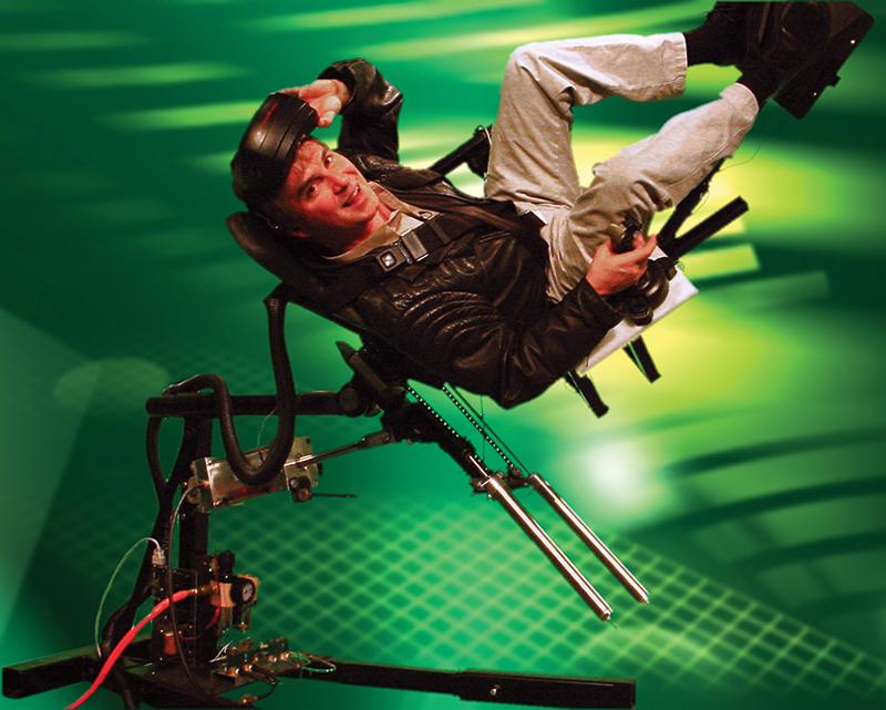
This is an example of a simulator I built that uses virtual reality goggles. No cabin is required.
Virtual Reality Waits for No One
Fifteen years is an eternity in computer years.
Both the hardware and software described in this project have been greatly surpassed by newer computers and interfaces.
I’m certain you will have many ideas for how these can be updated, and I’ll be including tips and tricks regarding simulation to help you do so.
That said, despite the older tech, the simulator itself is still flying beautifully after all this time (having given over 40,000 rides at air shows and events). Should you choose to use the same hardware/software, you’ll find yourself up and running in no time.
The Illusion of Flight/Simulator Theory
In designing your own simulator, it’s very important to understand how we perceive motion and our surroundings. Many aspects of making a good flying simulation are surprisingly counter-intuitive!
The first thing to take into account is how we as human beings sense motion. Our strongest sense of motion comes not from our inner ear, but from our visual senses.
If you were to stand in front of a movie screen staring straight ahead with no other visual cues and a flying scene was projected, most people will become so disoriented that without a handrail they will be unable to stand. However, if you were standing while watching the same scene on a TV, you would have no difficulty at all. This is because while the TV screen is projecting the same motion, your visual field isn’t filled by that motion. Plus, you see other visual cues around it that aren’t moving, so you are able to keep your balance.
For this reason, any simulator that does not fully enclose your vision will NEVER capture the feeling of flight ... not even to a small degree! While it may be fun to rock around in a moving chair, your brain will lock on to stable visual cues and all feeling of real flight will be lost.
So, the first rule of an immersive VR experience is: You must fully enclose your cabin or block all outside visual cues with virtual reality goggles (or the like).
The good news is we can also exploit this quirk of our own visual dominance to both simplify our simulator design and to radically increase the sensations in our ride. For example, most commercial simulator’s range of motion is limited to only six degrees of motion. Yet, the riders inside feel as if they are moving as much as 360 degrees!
The reason for this is that the motion base only needs to provide a few moments of acceleration in any given direction. Then, the video the rider is watching takes over to make them feel as if the motion is continuing.
The effect is very striking, and I have had riders who were absolutely certain they had done a full loop in a simulator which actually only moved a few degrees.
Next, ideally, your simulator’s cabin should be designed to move in conjunction with what is happening in your screen imagery. Motion should not be tied simply to joystick control as many simpler video games have done in the past. Locking motion to screen movements mimics how things feel in a real airplane, for example. Changes in thrust, rudder, and ailerons bring about unique attitudes in the airplane that are not dictated by stick position only.
Consider making a 360 degree turn in your car at 5 MPH mph or at 25 MPH. Though the wheel may be held in the same position, the forces you would feel would be entirely different at those two speeds. This is why simulator designers think in terms of accelerations and not movement or platform angles.
Another important reason to make certain that screen and platform motions are in sync is that most pilots will become nauseated within minutes when screen and platform are out of sync. It’s possible in a closed-loop system to throw the screen and platform out of sync intentionally, however.
This always struck me as a possibly useful way to induce spatial disorientation and/or test anti-nausea protocols.
It’s also a great way to make friends sick.
A Quick Warning
Before we go into the nuts and bolts of this build, I wanted to offer a quick and gentle warning.
Even though a simulator is a ground-based machine, the forces at work are still quite significant. Pistons, electric actuators, and even hydraulics often exert thousands of pounds in force on single points.
In early tests of the larger simulator, a broken weld nearly caused an eight foot plunge into metal scaffolding on a test “flight” I made.
After scrambling free, I had to laugh since I assumed I could tell the story of being the only guy who nearly was killed in a simulator crash! However, whenever I’ve told this story to simulator enthusiasts, they’ve been quick to offer their stories along the same lines. It almost seems the rule rather than the exception.
So, be careful in your design and testing, and treat this like a real vehicle, which it is — even if most of the motion is in our minds!
Deciding on an Actuator
There are three basic ways that most simulators are moved. These are with cylinders (hydraulic or pneumatic), servo/electronic, or manual weight shift operation. All of these have pros and cons.
For the purpose of this article, I’ll stick with a pneumatic system as this is robust, relatively inexpensive, and something I’ve loved designing with for years. Since the electronics to be described represent a full closed-loop system, they should lend themselves to any actuator you choose to employ. So, feel free to use your favorite.
One advantage of pneumatics in flight simulation is that you are essentially riding on air shock absorbers. This means your flights will be glass smooth with no mechanical sounds or vibrations.
Each axis on which your simulator can move is referred to as a DOF (degree of freedom). The simulator in this article requires two air cylinders, and is therefore a two DOF simulator (pitch axis and roll axis).
Once again, you are not limited to two DOF. Feel free to add rotational or even vertical acceleration actuators in your designs.
Figure 1 shows the simple hookup that will be used for each cylinder. Air from your compressor tank travels through a regulator to a 24V solenoid two-way valve. When this valve is opened, your cylinder will extend.
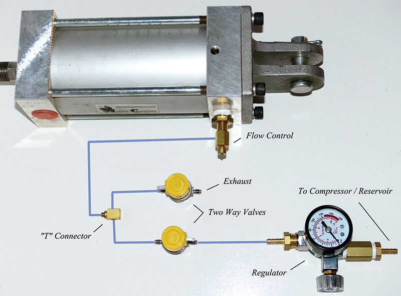
FIGURE 1
A second valve is connected to the system using a T fitting, and functions as an exhaust valve. When this valve is opened, the cylinder will retract. (The output from this valve can be connected to a muffler or long hose if you would like silent operation.)
Connected to the cylinder port is a needle valve for air flow control. This valve is important since it will determine the top speed with which your simulator will move, and prevent the air cylinder from extending too rapidly. (A wild ride is a good thing, but being thrown out of your seat is usually not ideal.)
Though I definitely recommend using all quality parts, I can’t resist mentioning that one builder used ordinary sprinkler valves for air valves and home-made PVC cylinders to move his project, and it worked! So, it’s even possible to build scrap box versions of this project.
Note: The simulator shown here used two cylinders for each axis. This was strictly because I happened to have smaller cylinders on hand when I built it. It is actually only necessary to use one cylinder for each axis by using a larger bore version.
In selecting your cylinder bore and stroke, determine the size you need based on your weight and your compressor’s PSI rating. Cylinder force and PSI info will be available from the particular manufacturer.
Building the Cabin
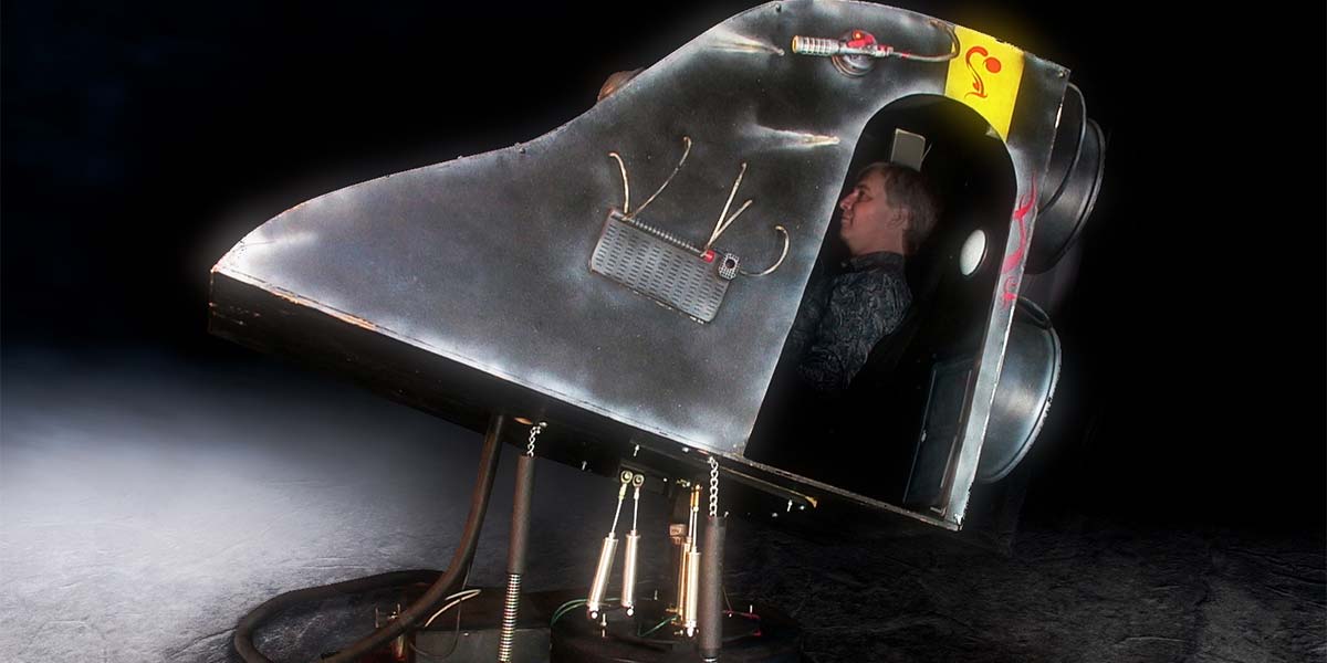
Figures 2 and 3 show the first successful and easily built prototype which flew for many years.
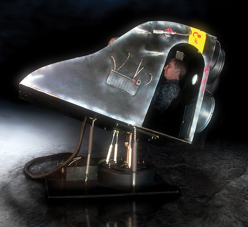
FIGURE 2
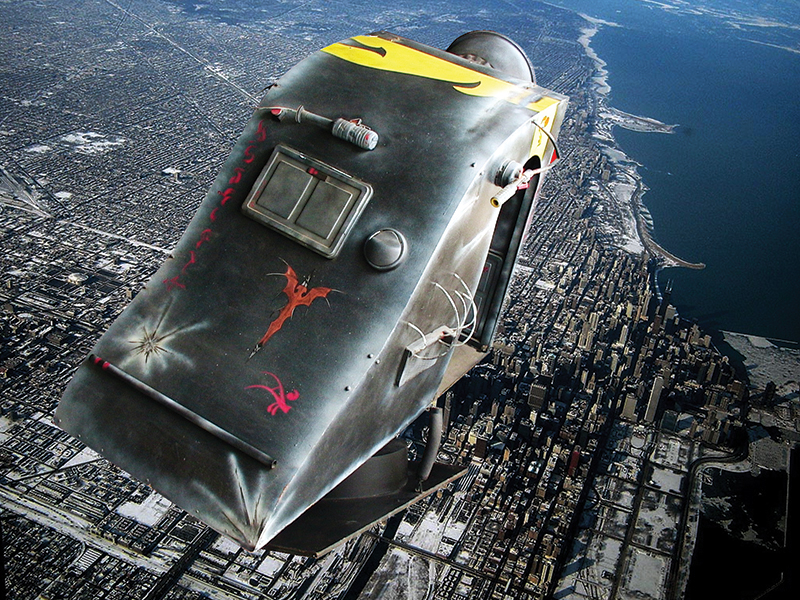
FIGURE 3
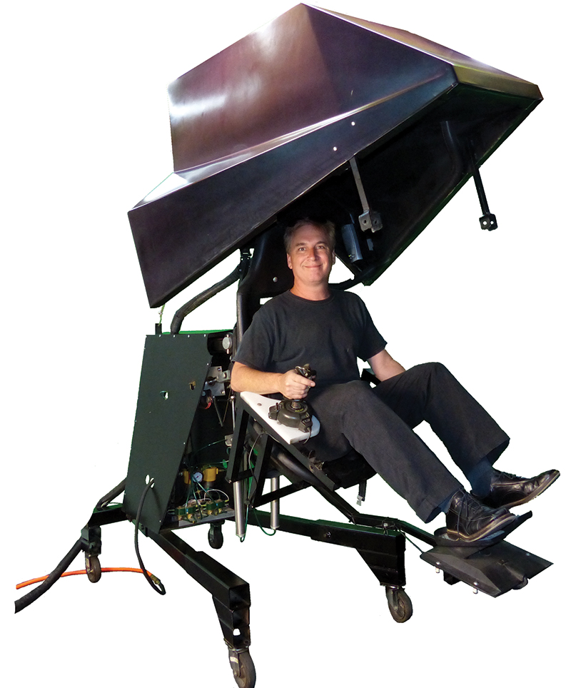
The design was intended to look like an “alien craft” for some air shows we did, but this cabin design looks just as great for a home simulator if simply painted black. The door is a simple curtain that was left off for the photograph to give a sense of size and rider position. Figure 4 shows the inside layout with video screen, joystick, seat, and rudder pedals.
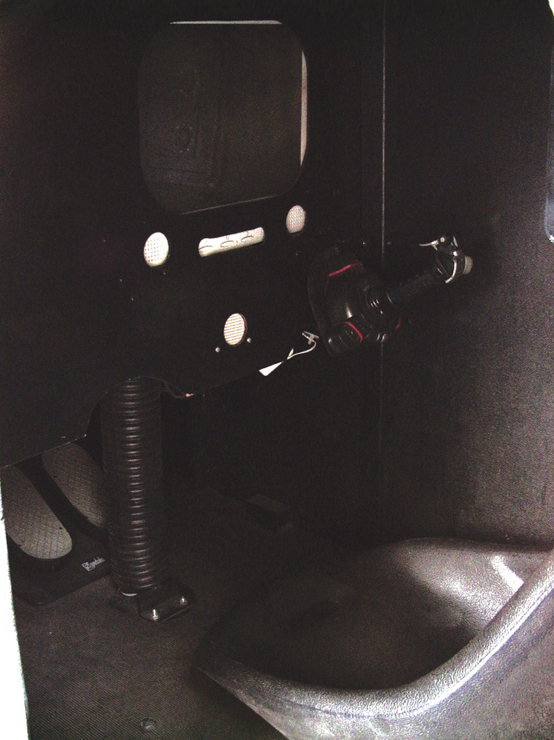
FIGURE 4
When I built this version, a 15” flat screen LCD was still expensive, but these days a much larger video screen and even multiple monitors for side views is possible. Cabin construction is incredibly light weight, inexpensive, and simple. The floor is made from 1/2” plywood, and the walls and ceiling are made from 1/8” 4’ x 8’ tempered hardboard.
Hardboard is available from all major lumber stores for about $9 a sheet, and bends easily into many shapes.
By gluing small wood blocks at all corners and along seams as needed, the your cabin’s hardboard panels can literally screw together. All seams are then reinforced, and gaps are filled using a simple construction adhesive such as Liquid Nails™. This design withstood many years on the road, and worked perfectly for riders up to 220 pounds.
If you’re not into carpentry, no problem! Figure 5 shows an even simpler cabin made using standard PVC pipe and fittings. By simply covering such a PVC frame with fabric or any other thin material, a very simple “hood” can be made for quick experimenting.
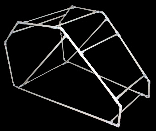
FIGURE 5
Ultimately, your cabin should be designed to fit your needs.
Mounting to a Pedestal
For this particular simulator, I chose a pedestal mounting system (Figure 6). This is nothing more than a scrap automotive universal joint (as you might find on a drive shaft) from a junkyard. Usually, these cost little or nothing.
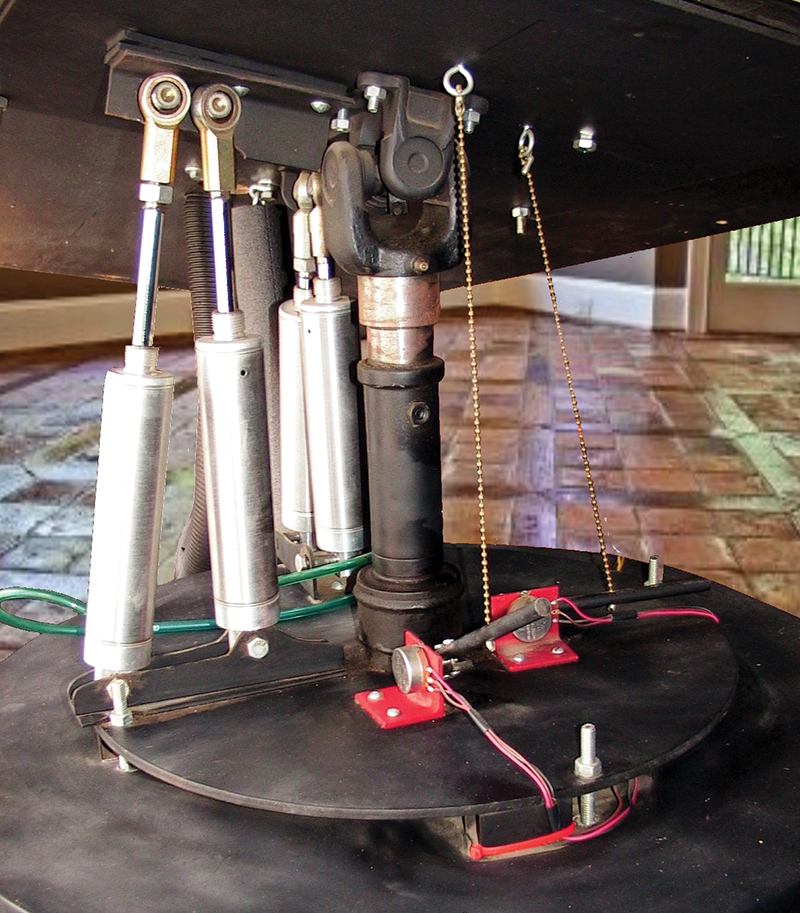
FIGURE 6
I hired a local welder for a few dollars to cut and weld this shaft to a large metal plate. Looking again at Figure 2, note that the pedestal is not centered under the cabin. It should be mounted so that it is far enough back on the cabin that some weight will always be on the front pitch cylinder. By keeping the cylinder under constant load, you will always have control of your platform’s position.
The same is true for your side roll axis. As seen in Figure 7, the pedestal mounts slightly behind and aft of the rider and simulator’s center of gravity to keep both the pitch and roll cylinders under constant load. You will also notice in the photo that I had two chains and springs attached to keep an additional load on each cylinder at all angles.
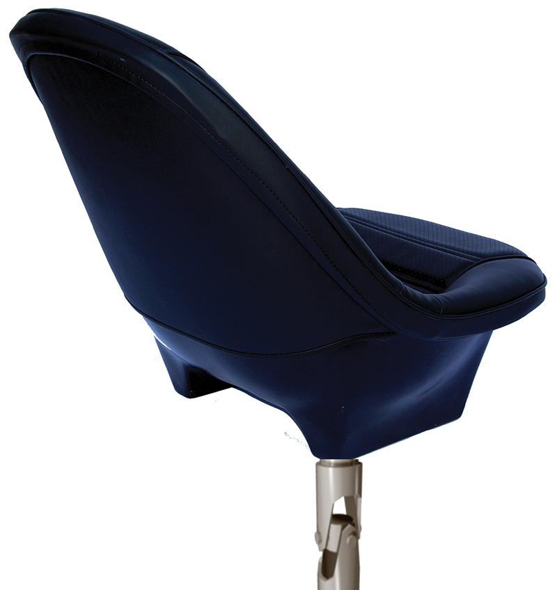
FIGURE 7
You may or may not find this necessary, but since I wanted a wild ride, I added the springs so that the tilt of the cabin would be as rapid and wide as possible on the return stroke of each cylinder.
The Electronics
Thanks to Weeder Technologies — whose ads I found in Nuts & Volts years ago — electronic connection of the original simulator to the computer was extremely simple. Let’s briefly talk about what the electronics do.
The Virtual Flyer is a complete closed-loop system, which is to say that the computer running the simulation monitors the exact position of the simulator platform and adjusts that position to match events on the screen approximately 20 times each second.
In order to accomplish this, your computer simply needs an input/output module capable of opening and closing the four air valves that move the simulator. It also needs to read the position of the platform via two feedback potentiometers.
Figure 6 shows the two feedback potentiometers on the base of the simulator. Attached to each potentiometer is a heavy armature and a length of chain that attaches to the base of the cabin.
One chain is attached to register pitch movement and one is to detect roll position. As the cabin moves, the chains raise and lower the potentiometer arms and the values are captured by the computer. These days, many modules exist that are capable of performing both functions and connecting via USB or other simple means to your computer.
In addition, many terrific microcontrollers could probably do the whole job without burdening the computer at all. So, you are not necessarily tied to the Weeder control boards I used (though the software I wrote would have to be modified for your board of choice). This is a key place where you may enjoy modernizing the design.
For the original Flyer, I used Weeder Tech’s Digital I/O Module (WTDIO-M) to operate the solenoid valves, and Weeder Tech’s analog input module to read the values from the two potentiometers.
Figure 8 shows the entire circuit board connected. As you can see, electronic control for the simulator is simply two Weeder boards and a set of IFR 540 MOSFETS which handle the load when opening and closing the four air valves.
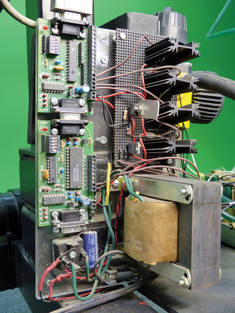
FIGURE 8
Figure 9 shows how the IFR 540s and potentiometers are connected between the Weeder board and the air valves. (Each of the pitch and roll connections are connected to the same IFR 540 circuit shown for pitch 1.)
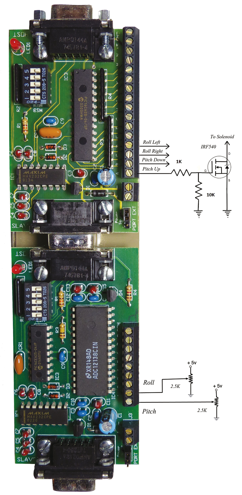
FIGURE 9
Software
Three pieces of software are needed for your simulator to fly:
- The software that controls the platform.
- Software that reads (and sends) screen position data from the game to the control software.
- A flight simulator program such as Microsoft Flight Simulator or Combat Simulator to fly with.
In operation, you will start the platform control and screen reading software in the background, then load the video game and off you go. As mentioned before, the design of this simulator is more than 15 years old and that fact shows up in the software most of all. Currently, the simulator software that I wrote is only proven to work with software from that time.
Both Microsoft Flight Simulator (through 2002) and Combat Flight Simulator from the same years work great, and are easily obtainable on eBay and elsewhere. They are still excellent programs even by today’s standards. In addition, the preferred platform for running this software is Windows 98.
So, an inexpensive older computer could be used as a dedicated flight simulator computer, or a modern computer can be set up to “dual boot” to Windows 98.
Of course, it might also be possible to use a compatibility mode in Windows to run older software. I have not tested this, and my experience with compatibility modes has been pretty poor.
Time to Take Off
I hope this article has whet your urge to take on a project like this. It really is a thrill to have your own F-16, ehem, I mean simulated F-16 waiting right in the next room for you at any time.
There is a burgeoning home simulator community to be found on the Internet with many extraordinary tips, ideas, and methods for maximizing the experience.
I’ll put together extensive downloads and videos showing all the inner workings close up, and provide links to many other sources of home simulator materials at www.noonco.com/flyerbuilder.
Let’s get building! NV
Parts List (of sorts)
(4) 1K 1/2 watt resistor
(4) 10K 1/2 watt resistor
(2) 2.5K potentiometers (highest quality possible)
(4) IRF540 MOSFETs
7805 voltage regulator (to provide 5V current to feedback potentiometers)
24V DC power supply (select amp rating to suit your chosen solenoid valves)
Weeder Technologies digital I/O module WTDIO-M
Weeder Technologies analog input module WTADC-M
Note: My Virtual Flyer's Weeder boards connected to the computer's serial port.
If your computer lacks a serial port, a USB to serial adapter cable has been tested with the Virtual Flyer and will work.
I do not have experience with newer USB based boards or if they can be accessed from Quick Basic.
(4) 24V solenoid valves (ideally 1/4" 150 PSI or higher)
Note: Larger air cylinders can run at lower pressures, so lower PSI air valves than previously mentioned can also work in that instance.
Parts Sources:
An extraordinary, inexpensive source for surplus solenoid valves and cylinders is www.surpluscenter.com.
For hoses and fittings including cylinder flow controls (needle valves), go to www.clippard.com.
Clippard's components are the highest quality.
I strongly recommend Clippard's needle valves such as the MNV-3P to serve as your cylinder flow controls.
Both the platform control software and the screen position software are available for download at www.noonco.com/flyerbuilder.
The original software was written by me in Basic and is therefore extremely easy to read and modify. I’m also putting up on the web page for your perusal all my original heavily commented source code and an explanation of how the code works. This should make it easy to rewrite or use the older source code as a jumping off point for connecting to your current favorite software.

