My first encounter with Parallax was through an ad that appeared on the back of Nuts & Volts in late 1993. Back then, they were introducing an SBC (single-board computer) called the BASIC Stamp. My cynical side thought it too good to be true, so I ignored it. Well, about six months later, I had a change of heart and decided to order the BASIC Stamp 1 starter kit. After dinner one evening, I opened the kit and started to experiment. The next time I looked at the clock it was past 10 AM the following morning! A few weeks ago, I started digging into the Propeller 2 (P2) and have found myself having more wildly-fun all-nighters!
People that know my history know that I’m biased (I once worked for Parallax; I’ve written extensively about their products; and 90% of my consulting work is for the Propeller 1), but still, I believe that I can objectively say that the Propeller 2 is a very cool device. Those who give it a try and experience true multi-core programming are going to have a lot of fun and be tremendously productive. There is a lot to the P2. What I’m hoping to do in this article is give an easy preview and show you how some of the neat new features can be leveraged in your applications.
What Took So Long?
Many will ask what took Parallax so long to finish the P2 — especially since the P1 was introduced way back in 2006. The answer ... human nature. It’s quite unusual for a microcontroller to be developed so publicly and for the manufacturer to incorporate user feedback and suggestions. Designs by committees always take longer, and when the committee giving input and feedback is literally hundreds of passionate users, things slow down.
That said, the hardware is done now and is very exciting — exactly what we would expect from Parallax, a company that has always been user-focused and done things a bit differently.
For the record, I was not part of the committee I just spoke of. I deliberately waited for the P2 hardware to be locked and Spin 2 (its native HLL) to be available before I spent time with it. Thankfully, the features that I hoped for (and that are not part of the P1) are built into the P2.
What’s the Same? What’s Different?
Being a member of the Propeller family, the P2 is multi-core; it has eight 32-bit processors that run simultaneously. Yes, simultaneously. I know that contrary information about Propeller behavior has been published in this magazine and others, but those statements were made by people who (I believe) don’t actually use the Propeller. As a person who has been programming the P1 for 14 years, believe me when I tell you that the [active] cores are all running at the same time. They do, of course, share time exchanging data with the hub (using round-robin access), but that is a small fraction of the core’s activity.
Okay, the eight-core model stayed the same, so what changed? These are the big hits:
- 512 kB of hub RAM (P1 has 32 kB)
- 64 I/O pins (P1 has 32)
- I/O pins have “smarts” for complex tasks
- Faster clock speed (300 MHz vs. 100 MHz)
- Instructions run in two clocks (vs. four in the P1)
- Better suited for external tools (compilers, debuggers, etc.)
- Cores have additional 2K of memory
- Cores can run code from hub RAM
- Cores support interrupts
- Cores support traditional debugging (single-step, etc.)
Again, these are the big hits in my mind; that said, there’s a lot more.
Everybody likes more memory and more speed, and we certainly get that with the P2. For those that will program in the high-level language Spin 2 (as I will), you’ll be especially happy with the performance improvements that are built on the new P2 architecture.
It starts with the P2 using two clocks per instruction instead of four. Over the P1, this doubles execution speed. In simple tests, I found that the same code running at the same clock speed as on a P1 (80 MHz is standard) runs about 16x faster on the P2.
How is this possible? As I just mentioned, speed is doubled by using half the number of clocks; the rest comes from the P2 architecture that’s designed to move data between the hub and the cogs very quickly. This is not to say that assembly (P2ASM) will not be required at times, but we can certainly get a lot more work done in the same amount of time now when coding in Spin.
Spinning It Up
The native language offered by Parallax for the Propeller is called Spin, which is bytecode interpreted. Chip (Gracey; the owner of Parallax along with his brother, Ken) likes to create bytecode interpreters, and has been successful doing it since the days of the BASIC Stamp 1 where he packed an effective embedded BASIC into a very small PICmicro.
Interpreters are not as fast as native assembly, but they do allow for better code density. Where speed and timing precision are critical (e.g., a WS2812 driver), the Propeller can run straight assembly code. In the P1, this meant starting another cog; in the P2, those P2ASM segments can be incorporated into high-level methods.
This is one of my favorite features of the P2, and I use it frequently. I’m not a person that likes to write a lot of assembly, but writing in small chunks — especially with an assembly as user-friendly as P2ASM — works nicely for me. If you’ve been shy about trying assembly, the P2 is a really great way to dip your toes into those waters.
For those who haven’t seen or used Spin, we’ll look at a few simple examples that will give you a sense of the language. You’ll no doubt recognize elements borrowed from other HLLs. It looks a bit like Python by using indenting to define code blocks, with operators borrowed from Pascal and C. It’s a small language and very easy to master. We’ll begin with the embedded version of “Hello, World!” which is to say that we’ll blink an LED. For visual interest, we’ll specify that the LED should be on for a quarter second, and off for three quarters of a second:
pub blinker(pin, cycles)
dira[pin] := 1
repeat cycles
outa[pin] := 1
waitcnt(cnt + (clkfreq / 4))
outa[pin] := 0
waitcnt(cnt + (clkfreq * 3 / 4))
This is native Spin 1 without the benefit of any libraries. To the embedded programmer with some experience, it’s quite sensible. That said, in the past several years, we’ve seen a lot of people who are makers, crafters, and cosplayers adding microcontrollers to their creative endeavors, and most of them don’t have the time to get as in-depth. For them, efficiency is usually not a goal; getting something to meet their aesthetic requirements and to do it very easily tends to be the focus.
Like C, Spin is small and lean. The idea is that “big” stuff should be handled by libraries. With that, we can make the blinker friendlier for newcomers:
pub blinker(pin, cycles)
repeat cycles
io.high(pin)
time.pause(250)
io.low(pin)
time.pause(750)
That’s easier to follow, isn’t it? This code does the same thing as the first version, but it buries the hardware details in libraries. If you’re wondering why the “easy” commands weren’t just built into the P1 version of Spin, it came down to available space in the cog to run the interpreter.
In the P2, cogs have more space to run code, and improvements in the way P2ASM operates means that more work can be done in the same space. This is the P2 version of the blinker — no libraries required:
pub blinker(pin, cycles)
repeat cycles
pinhigh(pin)
waitms(250)
pinlow(pin)
waitms(750)
Other commands for pin manipulation are pinwrite() to write a specific value; pintoggle() to flip the output state of a pin; pinfloat() to set the I/O state to input; and pinread() to read the input bit. By the way, all of these commands work with one pin or a group of contiguous pins, and for those who like to minimize typing, there are shorthand versions: pinh(), pinl(), pinw(), pint(), pinf(), and pinr().
Each of these instructions correspond directly to a P2ASM instruction, so while interpreted, they are very efficient. The Spin 2 interpreter has delay methods for microseconds and milliseconds: waitus() and waitms(). Note that these are based on the system clock frequency, which means that the maximum delay is related to the clock speed of the project.
The formula for determining the maximum delay is: 2^31/clock frequency. If you’re running a 200 MHz clock as I do, the maximum delay is about 10.74 seconds; that’s 10,737 milliseconds, or 10,737,418 microseconds. Longer delays can be created with loops or through the use of delta timing via the system counter. The P2 has a 64-bit system counter. To give you an idea of the magnitude of 64 bits, running that counter at 200 MHz would take 2,924.7 years to roll over! Like the P1, the P2 is a 32-bit machine, so it’s not easy to deal with the system counter directly. The good news is we don’t have to.
Spin 2 has a couple of methods that aid in differential timing: getms() and getsecs(). Both return the run time (milliseconds and seconds, respectively) since the P2 came out of reset. Many will recognize getms() as doing the same thing as millis() does for the Arduino. This is useful for event timing with millisecond granularity. For example:
startPoint := getms()
‘ do something
duration := getms() – startPoint
The getms() method returns an unsigned 32-bit value which means we can time an event of just over 49 days.
One of the great updates to Spin 2 is that a method can return more than one value:
pub sum_dif(a, b) : sum, dif
sum := a + b
dif := a - b
To use this method, we can do something like this:
theSum, theDifference := sum_dif(10, 5)
This will result in theSum being set to 15, and theDifference being set to 5. For those coming from Spin 1, let me point out some details. First, return value(s) must be specified in the function declaration line after a colon. The P2 doesn’t return anything by default (the P1 always returns a single value). If the method is to return one or more values, they must be declared. To support multi-value methods, the assignment operator ( := ) now allows multiple values. Here’s a convenient trick using the new multi-value assignment operator:
x, y := y, x
This line of code will swap the values in two variables without declaring a third, or having to use additional lines of code. There will be times when all the values returned from a method are not required. Thankfully, there’s no need to declare a scratch variable to accept a return value that won’t be used:
theSum, _ := suf_dif(10, 5)
The underscore character serves as a placeholder that instructs the compiler to ignore that return value. In this example, the difference value returned from sum_dif() is ignored. To see this in application, have a look inside my jm_serial.spin2 library.
There’s a method called get_nargs() that returns two numbers from a string, but for some format commands, only one is required.
I casually mentioned clock speed; this is how it’s configured in a P2 program:
_clkfreq = 200_000_000
The default design for the P2 uses an external 20 MHz crystal or oscillator. Setting the _clkfreq value engages PLL circuity to provide the target clock speed for the system. This is very useful for odd speeds that may be required for advanced features like HDMI output.
To specify a different crystal frequency, use this syntax before _clkfreq:
_xtlfreq = 12_000_000
Designs that use an external oscillator would use this syntax:
_xinfreq = 100_000_000
One of the main design goals and features of the Propeller — the P2 in particular — is to be very flexible, yet easy to configure.
Inline Assembly
As I stated before, P2ASM is a user-friendly assembly language. There are about 350 instructions, many of which do things that require multiple instructions in other processors. This is an advantage of having a hard-core assembly programmer like Chip design a microcontroller. It’s designed to do the work, and to do it with the least fuss for the programmer.
For those situations where a quick burst of precision speed is required, the P2 allows inline assembly. This will usually be placed into a method. For example, the method shown in Listing 1 will transmit WS2812b data on any pin, and there’s no need to launch another cog.
pub ws2812b(pin, count, p_colors) | outval, cycle
‘’ Assumes 24-bit colors are MSB aligned (red in byte3)
org
drvl pin ‘ make output
waitx ##WSRT ‘ allow reset
led_loop rdlong outval, p_colors ‘ get color
add p_colors, #4 ‘ point to next
mov cycle, outval ‘ swap R & G bytes
shr cycle, #16
setbyte outval, cycle, #3
shr cycle, #8
setbyte outval, cycle, #2
getct cycle ‘ start timing frame
rep #7, #24 ‘ 8 bits x 3 colors
rol outval, #1 wc ‘ get MSB
drvh pin ‘ pin high
if_nc waitx ##WST0 ‘ hold high bit timing
if_c waitx ##WST1
drvl pin ‘ pin low
addct1 cycle, #WSTC ‘ update cycle timer
waitct1 ‘ let low bit time finish
djnz count, #led_loop ‘ do next LED
end
LISTING 1.
I will admit that when I wrote this code and it worked the first time I was smiling like an idiot for the rest of the day. In situations where you just need to drive one or a few WS2812b pixels, you can drop this method right into your program (I will, of course, provide a library for it too).
So, how does inline assembly work in a bytecode interpreted language? When inline assembly is used, the method parameters, return values, and local variables are shuttled into the interpreter cog with the assembly code. It runs there and when finished, the parameters, return values, and local variables are returned as if they had been manipulated by Spin code in that method.
Yes, this requires a bit of overhead, but as I mentioned earlier, the P2 architecture is built to move things in and out of cogs very quickly. The overhead required for inline assembly is very small, and adds a lot of power and flexibility when writing code in Spin 2.
Smart Pins
Honestly, I think an entire book could be filled with the topic of P2 smart pins, so I’m going to stick to a few examples of things that users of other micros often wish they could do with the Propeller (without resorting to external hardware, that is).
Briefly, each of the P2’s 64 I/O pins can be configured as a standard tri-state I/O pin, or it can be configured to be “smart” with up to 31 different modes. Each smart pin can be accessed by any cog, and there are mechanisms to prevent collisions between cogs when multi-cog access of a smart pin is required. Smart pins are configured using three registers: mode, x, and y. Smart pins that provide data to the application will do so through their z register.
Let’s look at a real world example: PWM output on a pin. In the P2, this can be any pin. We could code this in place, but I’m encapsulating it in a library method to make things clean and easy to integrate into any application.
pub start(pin, duty, hz) | x
‘’ Configure smart pin for DMX-compatible PWM
‘’ -- pin - output pin (0..55)
‘’ -- duty - duty cycle of output 0 to 255 (100%)
‘’ -- hz - pwm output frequency
if (hz > 0)
pp := pin
x.word[1] := 255
x.word[0] := 1 #> ((clkfreq / 255) / hz) <# $FFFF
pinstart(pin, P_OE | P_PWM_SAWTOOTH, x, duty)
This method behaves very much like the analogWrite() function that you’ve seen with other micros, with two benefits: 1) You can specify the PWM frequency; and 2) You can run it on any number of pins. You’re not limited to which pin or how many can run PWM.
Okay, we’re coders, so let’s jump into the details to see how this smart pin function works. The PWM (sawtooth) mode has an internal counter that is controlled by the value in the upper 16 bits (word[1]) of the x register.
In this case, we want to be DMX and analogWrite() compatible, so that value is 255. By specifying sawtooth mode, the counter will increment from 1 to 255, and then start over.
The timing for each count is determined by the value in the lower 16 bits (word[0]) of x, which is specified in system ticks. To get this value, we divide the system clock speed by the counts in 100% (255) and then divide that by the target PWM frequency. This produces the number of system ticks per PWM bit.
Figure 1 illustrates the relationships between the duty cycle setting, the internal counter, and the PWM output using sawtooth mode. The duty cycle is passed to the smart pin through the y register. When the counter is incrementing, the output will be high when the duty cycle setting is the same or greater than the counter value. As soon as the counter exceeds the duty cycle, the output will go low. What this means is that a duty cycle of 0 will always be off and a duty cycle of 255 will always be on.
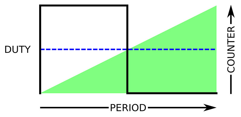
FIGURE 1.
The pinstart() method is used to configure the smart pin; it takes the pin number, mode, and x and y register values as parameters. Internally, smart pins use the DIRx bit to enable the circuitry; hence, floating the pin by writing 0 to the DIRx bit will disable the smart pin. If we want to revert a smart pin to standard I/O, the pinclear() method handles that. It disables the smart pin circuitry and writes zeroes to the mode, x, and y registers.
With many devices (e.g., motors), we don’t want to reconfigure the pin to change duty cycle. Once the PWM pin is up and running, changing the duty cycle is a matter of writing the new value to the pin’s y register; the update will take place on the next PWM cycle. We can wrap wypin() in a nice method for ease of use:
pub write(duty)
‘’ Update duty cycle of pwm pin
wypin(pp, 0 #> duty <# 255)
This updates the duty cycle and ensures the value written is legal (i.e., constrained between 0 and 255). We can now, of course, do the obligatory LED throb as seen in so many TV and movie props:
pub throb(pin, cycles, delay) | level
repeat cycles
repeat level from 0 to 254
led.write(level)
waitms(delay)
repeat level from 255 to 0
led.write(level)
waitms(delay)
Experienced LED users are thinking to themselves, “Yeah ... but that’s not going to look very good.” They’re right. Our eyes don’t perceive brightness in a linear manner; if you run the code above, the LED will seem to get very bright at first and then not change much. Thankfully, this is easily corrected with a look-up table (gamma correction).
I do a lot of work with LEDs and movie/TV props, so I created an object for them that uses smart pin PWM output and includes gamma correction to make the output appear linear to our eyes.
Here’s a better version of the LED throb routine:
pub throb(cycles, delay) | level
repeat cycles
repeat level from 0 to 254
led.write(led.gamma(level))
waitms(delay)
repeat level from 255 to 0
led.write(led.gamma(level))
waitms(delay)
The final version of that object — which is included in the downloads — allows gamma correction by default which simplifies the code even further.
I listed the ability to specify PWM frequency as an advantage. Let’s say we want to send a command through an IR LED. So long as we know the modulation frequency of the receiver, sending IR with the Propeller 2 is as easy as what you see in Listing 2.
pub sircs_tx(pin, cmd, bits)
‘’ Transmit Sony IRC code over IR LED
‘’ -- pin - connects to IR LED anode through resistor
‘’ * cathode to ground
‘’ -- cmd - command to transmit
‘’ -- bits - bit count in command
cmd rev= 31 ‘ align cmd.bit0 to bit31
irled.start(pin, 128, 38_000, false) ‘ 50% dc, 38kHz, no gamma
waitus(2400) ‘ 2.4ms start bit
irled.write(0) ‘ stop modulation
waitus(600) ‘ 0.6ms gap
repeat bits ‘ loop through bits
irled.write(128) ‘ enable pwm
waitus(((cmd rol= 1) & 1) ? 1200 : 600) ‘ set bit delay (1.2 or 0.6ms)
irled.write(0) ‘ led off
waitus(600) ‘ 0.6ms gap
LISTING 2.
I’m using the Sony IR protocol here because it’s so well known, but this process extends to other protocols as well. Figure 2 shows an oscilloscope trace of the output when transmitting 001_0010101 which is command 21 (power) for device 1 (TV) using 12 bits.
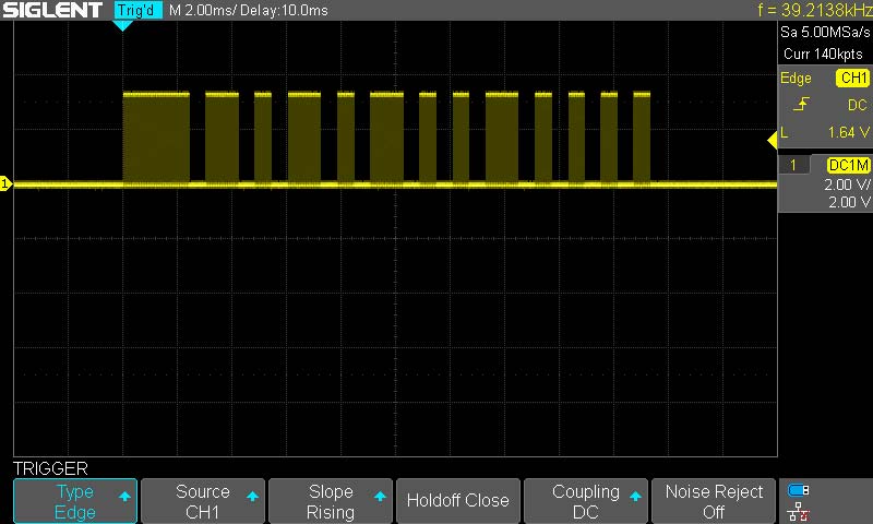
FIGURE 2.
Before we move on to look at other smart pin modes, let’s do one more thing with PWM: servo output. With a hobby servo, the frame time (period) is 20 milliseconds, and the pulse output for position will be from 600 to 2400 microseconds wide. This is the primary configuration method from my P2 servo object:
pub startx(pin, us) | x
‘’ Configure smart pin for servo output
‘’ -- pin - servo output
‘’ -- us - position in microseconds (600 to 2400)
sp := pin
x.word[1] := 20_000
x.word[0] := clkfreq / 1_000_000
usecs := 600 #> us <# 2400
pinstart(pin, P_OE | P_PWM_SAWTOOTH, x, usecs)
setup := true
By using the P2’s smart pins to handle servos, we can run as many as we want on any pins that we want, and there’s no impact on the execution of our main program because all of the pulse generation is happening in the smart pin circuitry. It doesn’t have to be “bit-banged” in an interrupt or another cog.
I think this method very clearly illustrates the relationship between the high (1) and low (0) words in the x register. As you can see, the high word is set to 20_000, which is 20 ms in 1 µs units. The low word of x is the system ticks in one microsecond. This lets us set the pulse width via the y register directly in microseconds.
A big part of the fun in creating libraries is crafting methods/functions to make the end-user’s life a little easier. Many servo libraries allow the user to specify position in degrees. I like flexibility, so my write() method allows degrees or microseconds by using a mode parameter:
pub write(mode, value)
‘’ Update servo
‘’ -- mode - 0 for degrees, 1 for microseconds
‘’ -- value - new angle or position value
if (setup)
if (mode == M_ANGLE)
angle := 0 #> value <# 180
usecs := angle * 10 + 600
else
usecs := 600 #> value <# 2400
wypin(sp, usecs)
There’s so much more to explore with the PWM modes of the P2. I think the next year is going to be very exciting seeing those modes exploited.
Now, I know that some of you are saying, “Hey, Jon, I want to read a potentiometer — can I do that without a lot of fuss now?” Yes. Yes, you can. Connect one side to ground, the other to 3.3V, and the wiper to an I/O pin.
The flexibility of the P2 means that we can turn any pin into an analog input, and we even have choices of range and resolution. To keep things easy, I created a simple analog library that lets me do this:
xaxis.start(X_POT, -100, 100)
The start() method configures the pin for analog input using what we would consider the “normal” range of ground to 3.3V (interestingly, the analog circuitry can read below ground and above 3.3V). The pin is calibrated, and range constants are set up. The current value of the potentiometer is accessed with the read() method:
panSpeed := xaxis.read()
If the wiper of this pot is connected to ground, panSpeed will be set to -100. If the wiper is moved to 3.3V, panSpeed is set to +100. Of course, values between the extremes are scaled for the defined range. What I’ve done is crafted code that is identical to the Arduino’s analogRead() and map() functions, and made them very easy to use through the methods in my analog object. I’ll leave you to explore that code; you’ll find it’s very simple.
There’s so much more to smart pins, but no space in a single article to cover them all — but let me list some of the other options:
- Asynchronous serial I/O (UART)
- Synchronous serial I/O (SPI)
- DAC output
- NCO
- Counters
- Quadrature encoder input
- USB host/device
Smart pins add a lot of horsepower, and most modes require very little code to use.
Tools. Tools. Tools.
I’m an unabashed Spin programmer, but for those of you who are not, there’s good news: You have a choice of languages with the P2. We’ll start with Forth, because it’s built in. You can begin to work with the P2 with nothing more than a USB connection and a terminal program.
So long as your board is not configured to boot from Flash or an SD card, open a terminal, set it to 115200 baud, and press “>”, the space bar, then Esc to boot into TAQOZ, the Forth environment built into the P2.
Why Forth? The main reason is that Forth is a self-hosting language — no special tool is required, so it can be accessed using a generic terminal from any OS. TAQOZ — was created by Peter Jakacki, a man who loves Forth, and uses it on the Propeller (P1 and P2) in his consulting work. Peter is a big contributor to the Propeller forums and seems quite happy to assist those wanting to give his Forth engines a go. He’s also created his own P2 board called the P2D2. You can see a photo of it in Figure 3.
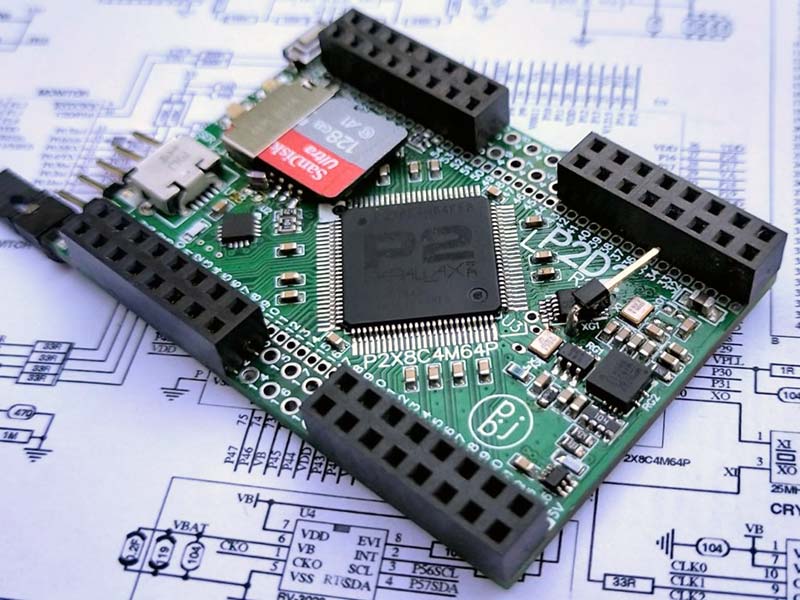
FIGURE 3.
Another regular in the Propeller forums, Eric Smith, has created a native compiler called FastSpin that understands Spin 1, PASM (P1), BASIC, C, and is now supporting Spin 2 and P2ASM. Many programmers use Eric’s compiler to get more speed from their existing Spin programs.
For those who prefer C, Eric also has you covered with the advantage of being able to mix code from other languages. For example, I wrote a test program in C for the P1 that used several of my Spin 1 object libraries. Like Peter, Eric is very helpful with forum members, and always seems keen to incorporate good ideas and suggestions provided by those using his compiler.
One of the first C compilers for the P1 was Catalina by Ross Higson. It has been updated for the P2, and as with the other tools, that development (especially libraries) continues. Ross puts together a nice installation package that provides a version of Code::Blocks that is ready to produce Propeller code. This simplifies getting started for new programmers.
For those who love BASIC, I already mentioned that FastSpin understands a dialect of BASIC, and recent forum posts suggest that Terry Hitt is porting his popular PropBASIC to the P2.
This was welcome news by many in the forums.
Finally, if you’re a Python programmer, you’ll be happy to know that microPython runs on the P2. This is very exciting given the multi-core approach of the P2. Hopefully, the folks at Adafruit will make a port of their CircuitPython (derived from microPython) available for the P2 as well. Python is becoming very important in education, and having it run on small micros is beneficial for students who have an interest in embedded design and coding.
It’s fair to say that Parallax tends to be Windows-centric. That said, they’re doing what they can to help other tool builders. The first version of the Spin 2 compiler (called PNut) was written by Chip in x86 assembly language — about 13,000 lines worth. We all have our favorite language, and x86 is Chip’s. Still, he recognizes that this doesn’t work for those wanting to craft tools that run in Linux or on the MacOS, so he’s in the process of porting that compiler to C.
Aside from allowing for cross-platform tools, having the compiler source and the Spin 2 interpreter source will serve as a template for those who want to create a custom bytecode compiler and interpreter for the P2.
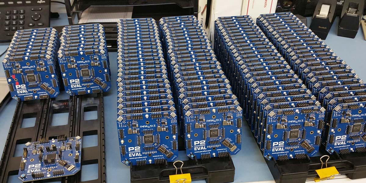
P2 Eval boards (Figure 4) and associated accessory kits, etc., are available at https://www.parallax.com/product/64000-es. Before long, we can also expect to see something on the order of a P2 Activity Board considering Parallax’s commitment to education and small robotics.
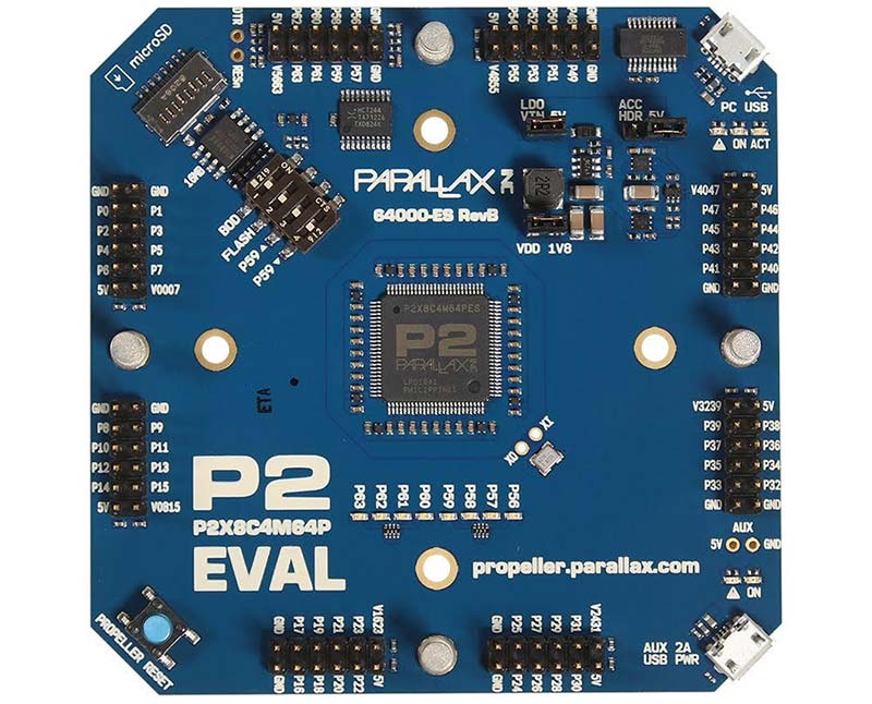
FIGURE 4.
As I write, some early adopters/testers are creating their own printed circuit boards. I’m working with two friends in the film industry on a board that we can all use for our SFX projects. By the time this is in print, there will be some nice reference designs to get started with.
Lock and Load
Should you consider the P2 as a weapon for your arsenal? Absolutely! You certainly wouldn’t choose it to blink a couple LEDs when an ATtiny will do. On the other side of that are projects like 3D printer controllers, robotics, industrial controls, drone flight controllers — advanced projects that will be easy to code given the P2’s multi-core architecture.
I’ve already started porting some of my big P1 client projects to the P2 and finding now that I’m having a much easier time of it. Yes, some of that is experience; a big chunk, though, is the unique and wonderful design of the P2 and how programmer-friendly it really is.
The P2 is flexible, powerful, and hides nothing from those wanting to explore. Give it a look, then give it a try. You’ll have fun with the P2 and have a great new tool in your kit. NV
Resources
Jon McPhalen
[email protected]
Parallax
www.parallax.com
Peter Jakacki
TAQOZ / P2D2 PCB
https://bit.ly/2R8QdZI
Eric Smith
FlexGUI / FlexSpin Compiler
https://github.com/totalspectrum/flexgui/releases
Ross Higdon
Catalina C Compiler
https://sourceforge.net/projects/catalina-c
Downloads
What’s in the zip?
All Code Files